
User's Manual


3-8 UltraEnterprise6000/5000/4000 Systems Manual—November1996
3
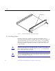
3. Pull the ends of both extraction levers outward simultaneously to unseat
the board centerplane connector from the centerplane receptacles.
See Figure 3-5 for the positioning of the levers.
Figure 3-5 CPU/Memory Board
4. If a board is not immediately replaced, a load board (Enterprise 6000
systems only) or a filler panel (Enterprise 4000 and 5000 systems only)
must be installed in its place.
See Section 3.2, “Filler Panels and Load Boards.”
3.4.1.2 RemovingaBoardfromaNonpoweredOnSystem
1. Use a Phillips #1 screwdriver to mechanically release the board from the
system card cage.
Insert the screwdriver into each quarter-turn access slot (the slots are located
on the left and right sides of the board front panel) and then turn a quarter
turn so that the arrow points to the unlocked position. See Figure 3-4.
Extraction lever
in extract/insert
position