
User's Manual


3-18 UltraEnterprise6000/5000/4000 Systems Manual—November1996
3
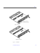
2. Ensure that both extraction levers are in the insert position (arrow
pointing outward), and that the quarter-turn access slots are unlocked
(arrow indicates unlocked position) as you slide the board toward the
centerplane receptacles.
See Figure 3-8 and Figure 3-9. The board will not seat fully unless the levers
are in this starting position and the access slots are unlocked.
Caution – DO NOT FORCE any board into a slot; this can cause damage to the
board and system. The board should insert and seat smoothly. If it binds,
remove the board and inspect the card cage slot for any obvious obstructions.
Also inspect both the board and the centerplane for bent pins or other damage.
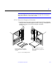
3. Push the board into the card cage, then simultaneously press both
extraction levers to seat the board on the centerplane.
Pushing both levers simultaneously avoids twisting the board and bending
the connector pins, and mates the board centerplane connector to the
matching receptacle on the centerplane. Do not press on board front panel to
seat it—doing so will damage the connector pins.
4. Mechanically lock the board to the system chassis by inserting a Phillips
#1 screwdriver into each quarter-turn access slot and then turning to the
locked position.
See Figure 3-8.
5. Replace or connect all necessary cables to the front of the board.
Note – The I/O board in slot 1 controls the internal SCSI tray devices.
Therefore, the external SCSI connector on the I/O board in slot 1 of a system
must be terminated with a SCSI terminator. See Figure 3-3.
6. Terminate the board SCSI connector if required, see above note.
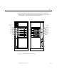
7. Once the board has been installed, a message similar to the following will
be displayed on the monitor (if the system is powered on):
Example depicts screen output when a new I/O board has been hot-plugged
into slot 6 of an operating Enterprise system:
NOTICE: I/O Board Hotplugged into Slot 6
NOTICE: Board 6 is ready to remove
!