Sun Blade™ X6240 Server Module Installation Guide Sun Microsystems, Inc. www.sun.com Part No. 820-3968-10, Rev. A June 2008 Submit comments about this document at: http://www.sun.
Copyright © 2008 Sun Microsystems, Inc., 4150 Network Circle, Santa Clara, California 95054, U.S.A. All rights reserved. Sun Microsystems, Inc. has intellectual property rights relating to technology embodied in the product that is described in this document. In particular, and without limitation, these intellectual property rights may include one or more of the U.S. patents listed at http://www.sun.com/patents and one or more additional patents or pending patent applications in the U.S.
Contents Preface 1. vii Setting Up the Server Hardware 1 Installation Overview and Terms 1 Inserting the Server Module ▼ 2 To Insert the Server Module 3 Powering On and Powering Off the Server Module ▼ To Apply Standby Power for Initial Service Processor Configuration ▼ To Power on Main Power for All Server Module Components ▼ To Shut Down Main Power Mode Using a Dongle Cable for Testing ▼ 2.
Option 1: Connecting to ILOM Through the Chassis Serial Connector ▼ To Connect to ILOM Through the Chassis Serial Connector Option 2: Connecting to ILOM Through a Dongle Cable ▼ To Connect to ILOM Using a Dongle Cable 19 19 20 ▼ To Log In and Out of the ILOM CLI ▼ To Log In and Out of the ILOM Web GUI Configuring the ILOM IP Address 3.
Solaris 10 Operating System User Information Solaris 10 User Documentation Solaris 10 OS Training 43 44 Using the Solaris Installation Program Sun Java Enterprise System Sun Studio 11 44 44 44 Reinstalling the Solaris Operating System Downloading Software 4.
vi Sun Blade X6240 Server Module Installation Guide • June 2008
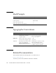
Preface This Sun Blade X6240 Server Module Installation Guide contains procedures for installing the server module in a chassis, connecting to the service processor, and configuring the preinstalled Solaris™ or Windows Server® 2003 R2 Operating System. Using UNIX Commands This document might not contain information about basic UNIX® commands and procedures such as shutting down the system, booting the system, and configuring devices.
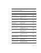
Shell Prompts Shell Prompt C shell machine-name% C shell superuser machine-name# Bourne shell and Korn shell $ Bourne shell and Korn shell superuser # Typographic Conventions Typeface* Meaning Examples AaBbCc123 The names of commands, files, and directories; on-screen computer output Edit your.login file. Use ls -a to list all files. % You have mail.
Note – The last two digits of the documentation part number identify the latest version of the product documentation that is available for download (or viewing online). For example: 820-xxxx-XX. Title Content Part Number Format Sun Blade X6240 Server Module Product Notes Late-breaking information about the server module. 820-3972 PDF HTML Sun Blade X6240 Server Module Getting Started Guide Basic installation information for setting up the server module.
Support, and Training Sun Function URL Support http://www.sun.com/support/ Training http://www.sun.com/training/ Product Updates For product updates that you can download for the Sun Blade X6240 server module, please visit the following web site: http://www.sun.com/download/ Find the Hardware Drivers section and click x64 Servers & Workstations. The Sun Blade X6240 server module site contains updates for firmware and drivers, as well as CD-ROM .iso images.
Sun Welcomes Your Comments Sun is interested in improving its documentation and welcomes your comments and suggestions. You can submit your comments by going to: http://www.sun.
xii Sun Blade X6240 Server Module Installation Guide • June 2008
CHAPTER 1 Setting Up the Server Hardware This chapter describes how to insert the Sun Blade X6240 server module into the chassis, how to power on and power off the server module, and how to connect the dongle cable to the server module.
2. Connect all cables, peripherals, and power cords to the chassis. See the installation guide for your chassis. 3. Power on the server module. See “Powering On and Powering Off the Server Module” on page 5. 4. Connect to the server module through the service processor on the chassis management module or through the service processor on the server module itself. This book assumes that the service processor software on the chassis, called the CMM ILOM, is already configured.
▼ To Insert the Server Module 1. Locate the desired server module slot in the chassis. 2. (Optional) Remove the slot filler panel, if applicable. Pull the lever out and eject the filler panel. Note – Other filler panels should remain in any unused slots as they ensure the chassis complies with FCC limits on electromagnetic interference (EMI). 3. Position the server module vertically so that the ejectors are on the right and extended outwardly.
FIGURE 1-1 Inserting the Server Module Into the Chassis 4. Push the server module into the slot until the server module stops. See Box 2 in FIGURE 1-1. 5. Rotate the ejectors down until they snap into place. The server module is now flush with the chassis and the ejectors are locked. See Boxes 3 and 4 in FIGURE 1-1.
Powering On and Powering Off the Server Module You have to apply only standby power to the server module at this point so that you can perform initial configuration of the service processor (SP). Procedures for powering on to main power mode and for shutting down from main power mode are also included in this section. ▼ To Apply Standby Power for Initial Service Processor Configuration Use this procedure to apply standby power to the service processor (SP) before initial configuration. 1.
2. Use a pointed object or stylus to press and release the recessed Power button on the server module front panel. When main power is applied to all server module components, the green Power LED above the Power button lights and remains lit.
▼ To Shut Down Main Power Mode To power off the server module from main power mode, use one of the following two methods: ■ Graceful shutdown. Use a ballpoint pen or other stylus to press and release the Power button on the front panel. This causes Advanced Configuration and Power Interface (ACPI) enabled operating systems to perform an orderly shutdown of the operating system. Servers not running ACPI-enabled operating systems will shut down to standby power mode immediately. ■ Emergency shutdown.
Using a Dongle Cable for Testing Your chassis ships with a dongle cable. The dongle enables you to plug devices directly into the front of the server module for testing. Caution – The dongle cable should be used only for configuration and service purposes. It should be disconnected from the server module when the configuration or servicing operation is completed. If you have a dongle cable connected to a server module, it must be removed before closing the door of a rack cabinet.
FIGURE 1-3 Dongle Cable Connections 2 3 1 Legend Connector Status 1 Dual USB 2.
10 Sun Blade X6240 Server Module Installation Guide • June 2008
CHAPTER 2 Setting Up the Server Software This chapter describes how to configure and access the Sun™ Integrated Lights Out Manager software, and how to set up the platform operating system and driver software.
Note – This chapter describes how to access ILOM through the command-line interface and web browsers. For other methods, see the Sun Integrated Lights Out Manager 2.0 User’s Guide (820-1188). What Is a Service Processor? A service processor (SP) is a component, located on the server module’s motherboard, that operates independently of the other hardware in the system. The SP has its own IP address and MAC address and is capable of operating regardless of the state of the other system hardware.
Note – The CMM ILOM is shipped with an identical preconfigured Administrator account, with user name root and the default password set to changeme. ILOM Connection Overview FIGURE 2-1 shows the connections to the server module ILOM.
Note – Option 1 and option 2 enable you to connect to ILOM without knowing ILOM’s IP address. These options provide access to ILOM’s command-line interface (CLI) only. Option 3 requires you to know ILOM’s IP address, but supports CLI and web GUI access. Most users configure ILOM’s IP address, then connect to it using Option 3. Instructions for configuring ILOM’s IP address are in “Configuring the ILOM IP Address” on page 23. ■ Option 1. Use the serial connector on the chassis to connect to the CMM ILOM.
2. Configure the terminal device or the terminal emulation software to use the following settings: ■ 8N1: eight data bits, no parity, one stop bit ■ 9600 baud (default, can be set to any standard rate up to 57600) ■ Disable hardware flow control (CTS/RTS) 3. Connect a serial cable from the serial port on the chassis to a terminal device. Refer to the chassis documentation for the location of the serial port. Note – The serial port requires the following pin assignments.
5. Log in to the CLI: a. Type the default user name, root. b. Type the default password, changeme. Once you have successfully logged in, the CMM ILOM displays its default command prompt: -> You are now connected to the CMM ILOM CLI. 6. Navigate to the server module ILOM by typing this command: -> cd /CH/BLn/SP/cli Where n is 0 through 9 for server modules 0 through 9 respectively. 7. Type the command start. A prompt appears. 8. Type y to continue or n to cancel.
The following display shows an example of the login screen. -> cd /CH/BL2/SP/cli /CH/BL2/SP/cli -> start Are you sure you want to start /CH/BL2/SP/cli (y/n)? y Password: Type the password to the server module ILOM. Sun(TM) Integrated Lights Out Manager Version 2.0.3.9 Copyright 2008 Sun Microsystems, Inc. All rights reserved. Use is subject to license terms. Warning: password is set to factory default. -> exit Type this command to exit the server module ILOM and return to the CMM ILOM. Connection to 10.6.
Option 2: Connecting to ILOM Through a Dongle Cable You can use the dongle cable to connect a terminal directly to the server module ILOM. FIGURE 2-2 shows a dongle cable connected to a server module. Caution – The dongle cable should be used only for configuration and service purposes. It should be disconnected from the server module when the configuration or servicing operation is completed.
Legend Connector Status 1 Dual USB connectors Used 2 Serial port connector Used 3 VGA video connector Used ▼ To Connect to ILOM Using a Dongle Cable 1. Connect a dongle cable to the server module. 2. Connect a terminal or terminal emulator to the RJ-45 connector (labeled as 2 in the figure) on the dongle cable. The ILOM login prompt appears. 3. Type the user name and password when prompted. The default user name is root and the default password is changeme. The server module ILOM prompt appears.
Logging In and Out of ILOM You can use either the ILOM command-line interface (CLI) or web GUI to access ILOM. ▼ To Log In and Out of the ILOM CLI ILOM supports Secure Shell (SSH) access to the CLI over the Ethernet. 1. Start an SSH client. 2. To log in to ILOM CLI, type: $ ssh root@ipaddress Where ipaddress is the IP address of the server SP. 3. Type your password when prompted. The default user name is root, and the default password is changeme. For example: $ ssh root@192.168.25.25 root@192.168.25.
FIGURE 2-3 Web GUI ILOM Login Screen 2. Type your user name and password. When you first try to access the web GUI, it prompts you to type the default user name and password. The default user name and password are: ■ Default user name – root ■ Default password – changeme The default user name and password are in lowercase characters. 3. Click Log In. The web GUI appears. 4. To log out of the web GUI, click the Log Out button at the top right of the web GUI. The ILOM log out screen appears.
FIGURE 2-4 22 ILOM Log Out Screen Sun Blade X6240 Server Module Installation Guide • June 2008
Configuring the ILOM IP Address This section describes how to view and set the ILOM IP address. It includes the following sections: ■ “To View the ILOM IP Address” on page 23 ■ “To Configure the ILOM IP Address Using BIOS Setup Utility” on page 23 ■ “To Configure the ILOM IP Address Using DHCP” on page 25 ■ “To Configure the ILOM IP Address Using the CLI” on page 26 ▼ To View the ILOM IP Address 1.
c. After you see the message, press F2. After some messages and screen changes, the BIOS Setup Utility appears. 3. Select the Advanced tab. The Advanced page appears. 4. Highlight IPMI 2.0 Configuration in the list, then select Enter. The IPMI 2.0 Configuration page appears. 5. Highlight LAN Configuration, then select Enter. The LAN Configuration page appears. 6. On the LAN Configuration page, under IP Assignment, select DHCP or Static.
▼ To Configure the ILOM IP Address Using DHCP This procedure uses DHCP to assign ILOM an IP address. 1. Verify that your DHCP server is configured to accept new media access control (MAC) addresses. 2. Obtain the server module ILOM MAC address from one of the following locations: MAC addresses are 12-digit hexadecimal strings in the format xx:xx:xx:xx:xx:xx where x represents a single hexadecimal letter (0–9, A–F, a–f). Write down the address for future reference.
b. Type the reset command: -> reset /SP DHCP automatically assigns ILOM an IP address when the server module restarts. 5. Find the IP address that DHCP assigned to the server module ILOM. See Step 8 in “To Configure the ILOM IP Address Using BIOS Setup Utility” on page 23. ▼ To Configure the ILOM IP Address Using the CLI This procedure describes how to manually configure the ILOM IP address using the CLI. 1.
4. Do one of the following: ■ To configure a static Ethernet configuration, type the following commands: -> set pendingipdiscovery=static -> set pendingipaddress=xxx.xxx.xx.xx -> set pendingipnetmask=yyy.yyy.yyy.y -> set pendingipgateway=zzz.zzz.zz.zzz -> set commitpending=true where xxx.xxx.xx.xx, yyy.yyy.yyy.y and zzz.zzz.zz.zzz are the IP address, netmask, and gateway for your ILOM and network configuration. To determine these addresses, see your system administrator.
-> cd /SP/network -> show /SP/network Targets: Properties: commitpending = (Cannot show property) ipaddress = 10.6.42.42 ipdiscovery = static ipgateway = 10.6.42.1 ipnetmask = 255.255.255.0 macaddress = 00:14:4F:3A:26:74 pendingipaddress = 10.6.42.42 pendingipdiscovery = static pendingipgateway = 10.6.42.1 pendingipnetmask = 255.255.255.
Setting Up Platform Operating System and Driver Software After configuring the server module ILOM network settings, you can configure the preinstalled Solaris 10 or Windows Server 2003 R2 operating system or install a supported Linux operating system and drivers. ■ If you want to use the preinstalled Solaris 10 Operating System, refer to “Configuring the Preinstalled Solaris 10 Operating System” on page 31.
30 Sun Blade X6240 Server Module Installation Guide • June 2008
CHAPTER 3 Configuring the Preinstalled Solaris 10 Operating System This chapter explains the steps for configuring the Solaris™ 10 Operating System (OS) that has been preinstalled on your server. The preinstalled version is Solaris 10 5/08 or later. Note – Unlike with SPARC® systems, you will not see the output of the preinstalled Solaris 10 image through a monitor when you power on the server. You will see the BIOS Power-On Self-Test (POST) and other boot information output.
Before You Begin Before you begin configuring the preinstalled Solaris 10 OS, do the following: ■ Perform initial configuration of the server’s ILOM and determine the server’s network settings, as described in “Connecting to the Server Module ILOM” on page 13. ■ Gather the information that you will need for the configuration, as listed in “Installation Worksheet” on page 32. Note that default values are indicated by an asterisk (*).
TABLE 3-1 Worksheet for Solaris 10 Configuration Your Answers: Defaults (*) Information for Installation Description or Example Language Select from the list of available languages for the Solaris 10 software. Locale Select your geographic region from the list of available locales. Terminal Select the type of terminal that you are using from the list of available terminal types.
TABLE 3-1 Worksheet for Solaris 10 Configuration (Continued) Information for Installation Description or Example Name service Name service If applicable, which name service should this system use? Domain name Provide the name of the domain in which the system resides. NIS+ and NIS Do you want to specify a name server, or let the installation program find one? DNS Provide IP addresses for the DNS server. You must enter at least one IP address, but you can enter up to three addresses.
TABLE 3-1 Worksheet for Solaris 10 Configuration (Continued) Your Answers: Defaults (*) Information for Installation Description or Example Default route Do you want to specify a default route IP address, • Specify One or let the Solaris installation program find one? • Detect One The default route provides a bridge that forwards • None* traffic between two physical networks. An IP address is a unique number that identifies each host on a network.
Configuring the Preinstalled Solaris 10 Operating System Note – Before you perform this procedure, you need to set up the service processor. If you have not done so, see Chapter 2. Use the information that you gathered in “Installation Worksheet” on page 32 as you perform the configuration. After configuring the server module ILOM, you can configure the preinstalled Solaris 10 Operating System (OS) by using the service processor to connect to the system console.
2. Verify that the communication properties of the service processor are set to the defaults. For example: -> show /SP/serial/host /SP/serial/host Targets: Properties: commitpending = (Cannot show property) pendingspeed = 9600 speed = 9600 Commands: cd show 3. If the speed is anything other than 9600, change it by using the command: -> set /SP/serial/host pendingspeed=9600 commitpending=true 4.
▼ To Redirect the Console Output to the Video Port (Optional) The server module’s console is automatically directed to the serial port. GRUB, the open source boot loader, is the default boot loader in the Solaris OS for x86-based or x64-based systems. The boot loader is the first software program that runs after you power on a system. 1.
Configuring X6240 Server Module RAID Drives After you configure the Solaris OS, you might need to configure the RAID drives. RAID Drive Overview The Sun Blade X6240 server module has two optional RAID expansion module (REM) cards. You can access RAID configuration through the REM card BIOS. To access the LSI REM card BIOS, press CTRL-C during the system boot. To access the Sun StorageTek REM card BIOS, press CTRL-A during the system boot.
RAID Drive Options TABLE 3-3 shows the RAID drive options.
If you choose the preinstalled Solaris OS and want to make the OS part of a RAID set, and if you are using the LSI REM card only, perform the following procedure to update the preinstalled Solaris OS to a mirrored RAID set. As noted in TABLE 3-3, only IM (Integrated Mirror) allows data on the primary hard disk drive (HDD) to be preserved or merged into an array of disks. This procedure describes how to create a mirror image of the OS before or after the Solaris installation.
Creating a RAID Set to Incorporate a Preinstalled OS Using the Sun StorageTek REM Card The Sun StorageTek REM card enables you to choose from many RAID configurations. How you configure your system depends on your system requirements and the available hard disk drives in the system. This procedure describes how to mirror the preinstalled Solaris OS.
8. Click the screen to activate the Managed Systems List. 9. Double-click the local machine (it is displayed by IP Address of the Primary ENET connection). A prompt appears. 10. At the prompt, log in as root, using the OS password that was assigned during Solaris installation. 11. Click the SUN STK RAID Controller. All attached hard disk drives on Enclosure 0 and 1 appear. Tip – HDD0 (OS) should be Enclosure 0 Logical Volume 1. 12.
Solaris 10 OS Training Sun provides flexible training options that accommodate your personal schedule and learning style. The training options include instructor-led, web-based online, CD-ROM, and Live Virtual Class. For Solaris 10 Training and Certification options at a glance, go to: http://www.sun.com/training/catalog/solaris10.
application performance analysis and debugging of mixed source language applications. The tools offer multi-platform support, compatible with gcc, Visual C++, C99, OpenMP, and Fortran 2003. Reinstalling the Solaris Operating System If you want to reinstall the Solaris OS or to install a different version of the Solaris OS, you can install the OS in one of several ways, including by using DVD and network (using the Jumpstart Enterprise Toolkit [JET]).
46 Sun Blade X6240 Server Module Installation Guide • June 2008
CHAPTER 4 Configuring the Preinstalled Microsoft Windows Server 2003 R2 Operating System This chapter describes how to complete the intial setup of the preinstalled Microsoft Windows Server 2003 R2 operating system.
Before You Begin Before you begin the initial setup of the preinstalled Windows Server 2003 R2 operating system, you should review the “Hardware and Software Prerequisites” on page 48. Hardware and Software Prerequisites Ensure that the following hardware and software prerequisites are met prior to powering on the server: ■ Properly Installed Sun Blade 6000 Modular System.
For additional information about which console option to select (Sun ILOM or local), see “Connecting to the Server Module ILOM” on page 13. Initial Setup of Preinstalled Windows Server 2003 R2 OS Follow these steps to boot the Windows preinstalled image, as well as to configure the initial Windows operating system settings for language, licensing, date and time, and network. ▼ To Perform the Initial Setup of the Preinstalled Windows OS 1.
3. In the Welcome to Windows Setup dialog, click Next and continue the setup process by following the on-screen instructions. The following table summarizes the Windows Setup dialogs in the order in which they appear, as well as the actions required to complete them. For additional information, refer to Microsoft’s documentation. Windows Setup Screen Name Action Required Welcome to Windows Setup Wizard Click Next. License Agreement If you accept the license agreement, click Next.
RAID Drive Overview The Sun Blade X6240 server module has two optional RAID expansion module (REM) cards. You can access RAID configuration through the REM card BIOS. To access the LSI REM card BIOS, press CTRL-C during the system boot. To access the Sun StorageTek REM card BIOS, press CTRL-A during the system boot. TABLE 4-1 Sun Blade X6240 REM cards REM cards Press for BIOS Sun StorageTek CTRL-A LSI 3081E CTRL-C The server module has the preinstalled OS on hard disk drive 0 (HDD0).
RAID Drive Options TABLE 4-2 shows the RAID drive options.
If you choose the preinstalled Windows Server 2003 R2 OS and want to make the OS part of a RAID set, and if you are using the LSI REM card only, perform the following procedure to update the preinstalled Windows Server 2003 R2 OS to a mirrored RAID set. As noted in TABLE 4-2, only IM (Integrated Mirror) allows data on the primary hard disk drive (HDD) to be preserved or merged into an array of disks.
Creating a RAID Set to Incorporate a Preinstalled OS Using the Sun StorageTek REM Card The Sun StorageTek REM card enables you to choose from many RAID configurations. How you configure your system depends on your system requirements and the available hard disk drives in the system. This procedure describes how to mirror the preinstalled Windows Server 2003 R2 OS.
6. Click on the SUN STK RAID Controller. All attached hard disk drives on Enclosure 0 and 1 appear. Tip – HDD0 (OS) should be Enclosure 0 Logical Volume 1. 7. To mirror the OS, right-click Logical Device 1 and choose Expand or Change Logical Device. 8. Choose the appropriate RAID option (in this example, RAID 1 for Mirror). 9. Choose a disk to mirror the OS with, from the physical disk list. Select the hard disk drive that best fits your needs. 10.
Important Information After completing the Windows setup, refer to these sections about finding additional information about x64 Server Updates or the x64 Windows Server 2003 R2 Recovery Media Kit: ■ “Sun Link” on page 56 ■ “Recovery Media Kit” on page 57 Sun Link From the Windows operating system Start menu, you can conveniently obtain x64 server updates, view online documentation, and install supplemental software by clicking Sun Link Online Information (see FIGURE 4-1 and FIGURE 4-2).
FIGURE 4-2 Sun Supplemental Software Recovery Media Kit If you need to restore your system to the default preinstalled Windows operating system, follow the directions in the Sun x64 Servers Windows Server 2003 R2 Recovery Installation Guide that is enclosed in the optional Recovery Media Kit. If you do not have the Recovery Media Kit, contact your support representative. Note – The optional Recovery Media Kit must be ordered separately. By default, it is not shipped with the preinstalled Windows HDDs.
58 Sun Blade X6240 Server Module Installation Guide • June 2008
Index C chassis management module (CMM) ILOM, 12 chassis management module see CMM chassis, defined, 1 CMM, defined, 1 command line interface (CLI) SSH log in, 20 SSH log out, 20 D defined, 1 introduction, 11 serial connection, 14 SSH log in, 20 SSH log out, 20 IP address configuring through BIOS Setup utility, 23 configuring through DHCP, 25 L default root password, 20 dongle cable, 8 driver updates, x Dynamic Host Control Protocol (DHCP), 25 log in CLI and SSH, 20 log out CLI and SSH, 20 LSI REM car
P U password, root, 20 PCI EM MAC address, 32 power powering off, 7 powering on standby power, 5 preconfigured ILOM Administrator account, 12 product updates, x USB device connection, 9, 19 R V video port redirection, 38 W Windows Operating System configuring the preinstalled OS, 47 prerequisites, 48 RAID, 39, 51 RAID Expansion Module (REM), 39, 51 root password, 20 S Secure Shell (SSH) CLI log in, 20 CLI log out, 20 serial port connector, 9, 19 server module connecting through the SP IP address, 36