Sun Blade™ X6450 Server Module Installation Guide Sun Microsystems, Inc. www.sun.com Part No. 820-3535-12 September 2008, Revision A Submit comments about this document at: http://www.sun.
Copyright © 2008 Sun Microsystems, Inc., 4150 Network Circle, Santa Clara, California 95054, U.S.A. All rights reserved. This distribution may include materials developed by third parties. Sun, Sun Microsystems, the Sun logo, Java, Netra, Solaris, Sun Ray, Sun™ ONE Studio, Sun Blade X6450 Server Module, Sun StorageTek™ RAID Manager software and Sun company logo are trademarks or registered trademarks of Sun Microsystems, Inc., or its subsidiaries, in the U.S. and other countries.
Contents Preface 1.
GRUB 12 Windows Bootloader 12 Accessing BIOS Configuration Utilities and Selecting a Boot Device ▼ To Configure Netboot or Compact Flash Boot in the BIOS ▼ To Configure the QLogic Fibre Channel in the BIOS ▼ To Configure the Emulex Fibre Channel PCIe ExpressModule in the BIOS 14 ▼ To Load an OS Over the Network (Netboot) RAID Configuration 15 To Configure the Sun Blade RAID 5 Expansion Module ▼ To Configure the Sun Blade 0/1 RAID Expansion Module 17 Installing and Configuring the Server Mod
▼ To Connect to the ELOM CLI 29 Configuring the Service Processor’s Network Settings (Optional) ▼ 30 To Configure the Service Processor’s Network Configuration: Accessing the System Console 31 ▼ To Access the System Console Directly ▼ To Access the System Console Using the ILOM CLI 32 ▼ To Access the System Console Using the ELOM CLI 32 ▼ To Access the System Console Using the ILOM Web GUI 33 ▼ To Access the System Console Using the ELOM Web GUI 35 Dongle Cable Connections 30 31 38
▼ To Rescan Disk Drives With the ACU ▼ To Perform a Secure Erase on Disk Drives With the ACU ▼ To Stop a Secure Erase in Progress With the ACU 52 Using the -Select Utility to Modify REM Settings 52 53 ▼ To Start Using a -Select Utility ▼ To Apply Changes and Exit a -Select Utility ▼ To Modify General Settings With a -Select Utility ▼ To Modify SAS-Specific REM Settings With a -Select Utility 53 Using the Disk Utilities to Manage Disk Drives 53 54 56 ▼ To Format or Verify a Disk Drive
Preface This Sun Blade X6450 Server Module Installation Guide contains procedures for installing the server module in a chassis, and connecting to the service processor administrator account. Using UNIX Commands This document might not contain information about basic UNIX® commands and procedures such as shutting down the system, booting the system, and configuring devices.
Shell Prompts Shell Prompt C shell machine-name% C shell superuser machine-name# Bourne shell and Korn shell $ Bourne shell and Korn shell superuser # Typographic Conventions Typeface* Meaning Examples AaBbCc123 The names of commands, files, and directories; on-screen computer output Edit your.login file. Use ls -a to list all files. % You have mail.
Translated versions of some of these documents are available at the web site described above in Simplified Chinese, French, and Japanese. English documentation is revised more frequently and might be more up-to-date than the translated documentation. For all Sun hardware and software documentation, go to the following URL: http://docs.sun.com Documentation, Support, and Training Sun Function URL Documentation http://docs.sun.com/ Support http://www.sun.com/support/ Training http://www.sun.
or resources. Sun will not be responsible or liable for any actual or alleged damage or loss caused by or in connection with the use of or reliance on any such content, goods, or services that are available on or through such sites or resources. Sun Welcomes Your Comments Sun is interested in improving its documentation and welcomes your comments and suggestions. You can submit your comments by going to: http://www.sun.
CHAPTER 1 Introduction This chapter contains the following topics: ■ “Terms and References Used in This Book” on page 1 ■ “Installation Overview” on page 2 ■ “Routine Power On and Power Off” on page 3 ■ “About Diskless Servers” on page 5 ■ “About the Boot Process” on page 10 ■ “RAID Configuration” on page 15 ■ “Installing an Operating System” on page 17 ■ “Directing Console Output” on page 17 ■ “Accessing BIOS Configuration Utilities and Selecting a Boot Device” on page 13 Terms and Refe
■ Embedded Lights Out Manager (ELOM) – Earlier server modules were shipped with an ELOM. Current server modules can be downgraded to the ELOM, for compatability with older server modules. See the ELOM-to-ILOM Migration User’s Guide for details. References to other manuals are in italic text. These manuals should be available on the server module’s section of http://docs.sun.com. Installation Overview The following overview outlines the steps to install the server module.
■ To install a supported Windows operating system, see the Sun Blade X6450 Server Module Windows Operating System Installation Guide. Routine Power On and Power Off This section describes how to apply standby power to the server module so you can operate the service processor. It also includes procedures for powering on and for shutting down the server module. Note – You can also power on and power off the server module remotely using the service processor.
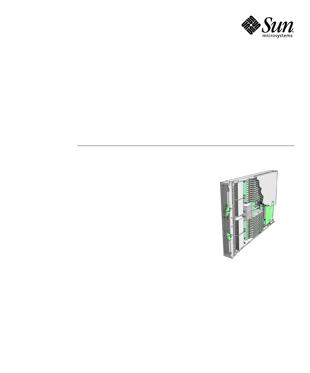
FIGURE 1-1 Server Module Front Panel Figure Legend 1 White LED - Locate - A service processor command causes the locate LED to blink. - You can also control the locate LED manually by pressing it momentarily to toggle its state, turning it On or Off.
■ Graceful shutdown. Use a non-conducting pointed object, such as a stylus, to press and release the Power button on the front panel. This causes Advanced Configuration and Power Interface (ACPI) enabled operating systems to perform an orderly shutdown of the operating system. Servers not running ACPI-enabled operating systems will shut down to standby power mode immediately. ■ Emergency shutdown. Press and hold the Power button for four seconds to force main power off and enter standby power mode.
■ Installing the operating system on a remote drive, which might be in the chassis (connected through the SAS-NEM module to a Sun Blade 6000 Disk Module) or outside the chassis, in a storage device such as a SAN. See “Connecting to SAS Devices” on page 7 and “Connecting to Exterior Storage Devices Using a Fibre Channel Connection” on page 10 The following sections describe methods of configuring remote drives: ■ “Connecting to SAS Devices” on page 7.
Solid State Disk Drive (SSD) The SSD is a 32-gigabyte solid-state SATA drive that mounts on the motherboard. Note – This feature requires a F540-7821-01 or newer motherboard, with 2.0 software installed. The motherboard part number appears on the motherboard, and can be read using the service processor. When an SSD is present, it appears as a disk device, and you can install an operating system on it. Note the following conditions: ■ The SSD can only be driven by the onboard SATA controller.
The following devices require software 2.0 or newer. ■ Sun Blade RAID 5 Expansion Module ■ Sun Blade RAID 0/1 G2 Expansion Module ■ Sun Blade 6000 Multi-Fabric Network Express Module The following devices require a F540-7821-01 or newer motherboard, with 2.0 software installed. The motherboard part number appears on the motherboard, and can be read using the service processor.
FIGURE 1-2 Connections to a SAS NEM Module Internal Connection to a Sun Blade 6000 Disk Module Inside the chassis, the Sun Blade 6000 Disk Module provides eight SAS drives. The Sun Blade 6000 Disk Module and the Sun Blade X6450 Server Module work in pairs, with the server module in an even-numbered slot, directly to the left of the disk module. Thus, the pairs can be in slots 0+1, 2+3, 4+5, 6+7, or 8+9.
Connecting to Exterior Storage Devices Using a Fibre Channel Connection The Sun Blade X6450 supports connections to an external SAN over a fibre channel link provided by a PCIe ExpressModule card in the corresponding PCIe ExpressModule slot. The PCIe ExpressModule card provides a fibre channel connection to the external SAN. FIGURE 1-3 shows the configuration. FIGURE 1-3 PCIe ExpressModule with Fibre Channel and SAN The chassis supports two PCIe ExpressModule slots for each server slot.
■ BIOS – Allows you to select a hardware device to boot from, and to configure other aspects of system operation ■ Bootloader– After the BIOS exits, the bootloader offers a selection of configured operating systems BIOS and BIOS Configuration Utilities When you power on your server module, it completes its self-test and then displays a series of messages that offer a chance to access and configure the BIOS. ■ If you do nothing, the server module boots from the default device.
Bootloaders are commonly used for two types of selections: ■ Booting different operating systems. For example, if you have installed the Solaris and Linux operating systems on different drives, or on partitions of the same drive, you can use the bootloader to select between them. ■ Booting the same operating system with different parameters.
Accessing BIOS Configuration Utilities and Selecting a Boot Device Because the Sun Blade X6450 is a diskless server, it most likely requires an option card to connect to its hard drives. In most cases, the option card must be configured using the BIOS configuration utility before you can install an operating system. ■ If your operating system installation procedure offers a selection of bootable devices, the procedures in this section might be unnecessary.
▼ To Configure Netboot or Compact Flash Boot in the BIOS 1. Power on the server module. 2. Press F2 to access the BIOS. 3. Navigate to the Boot page. 4. Select the Boot Device Priority option. 5. Select a boot device from the menu. Promote it to the top of the list by pressing + or - until it is at the top of the list. 6. Save your changes. ▼ To Configure the QLogic Fibre Channel in the BIOS 1. Power on the server module. 2. Use Ctrl-Q to open the QLogic BIOS configuration utility. 3.
4. Enable the PCIe ExpressModule as a boot device. See the documentation for your PCIe ExpressModule for details. When you boot the system, the BIOS will list drives connected to the PCIe ExpressModule and allow you to select them as the boot drive. 5. (Optional) Configure volumes and RAID arrays as required. See the documentation for your PCIe ExpressModule for details. 6. Save your changes.
■ See “To Configure the Sun Blade 0/1 RAID Expansion Module” on page 16 to use the BIOS configuration utility. ■ See the Sun LSI 106x RAID User’s Guide for additional details, and for instructions to configure RAID after the operating system is installed. ▼ To Configure the Sun Blade RAID 5 Expansion Module 1. Power on the server module. 2. Use Ctrl-A to open the configuration utility. 3.
Installing an Operating System After you have installed your server, you can install an operating system and drivers. Your server module supports the Solaris, Linux, VMware, or Windows operating systems. ■ For details about installing a supported VMware, Linux, or Solaris operating system, refer to the Sun Blade X6450 Server Module Operating System Installation Guide (820-3536).
18 Sun Blade X6450 Server Module Installation Guide • September 2008
CHAPTER 2 Installing and Configuring the Server Module This chapter provides instructions for installing and configuring the server module.
2. Remove the filler panel. Pull the lever out and eject the filler panel. Do not discard the filler panel. Caution – Do not operate the system with empty slots. Always insert a filler panel into an empty slot to reduce the possibility of module shutdown. 3. Position the server module vertically so that the ejectors are on the right. The following illustrations show the server module being inserted into the Sun Blade 6000 modular system; your chassis might differ. See box 1 in FIGURE 2-1 [1].
FIGURE 2-1 Inserting the Server Module Into the Chassis 4. Push the server module into the slot until the server module stops. See FIGURE 2-1 [2]. 5. Rotate the ejectors down until they snap into place. The server module is now flush with the chassis, and the ejectors are locked. See boxes 3 and 4 in FIGURE 2-1 [3,4]. If the chassis is powered on, the server module comes up to standby power. The green OK LED on the front panel flashes and the blue OK to Remove LED remains on. See FIGURE 1-1.
■ The blue, amber, and green status LEDs blink three times, at one second invervals. ■ After this, the green LED blinks at one-second intervals until the SP starts IPMI services. When the IPMI services are running: ■ If the system is powered on, the green LED stays lit. ■ If the system is powered off, the green LED blinks. Accessing and Configuring the ILOM The server module includes a service processor integrated into the motherboard. It can be either an ILOM or an ELOM.
Displaying the Service Processor’s (ILOM) IP Address Use the following procedure to display the ILOM’s network configuration, including including the IP address of the ILOM SP, using the CMM ILOM. This procedure also verifies that the ILOM is working correctly and that you can access it through the CMM ILOM. ▼ To Display the Service Processor’s (ILOM) IP Address 1. Log in to the CMM ILOM CLI. 2. Type the command: show /CH/BLn/SP/network where n is the server module number or chassis slot ID.
▼ To Connect to the ILOM Web GUI Note – To improve response times, disable the browser proxy server (if used). If you do not know the ILOM’s IP address, find it as described in “Displaying the Service Processor’s (ILOM) IP Address” on page 23 . Follow these steps to log in to the ILOM web interface: 1. To log in to the web interface, type the IP address of ILOM into your web browser. The web interface Login page appears. FIGURE 2-2 Login Page 2. Type your user name and password.
Note – After you log in to ILOM using the default user name and password, you should change the the ILOM root account password (changeme). See the Sun Integrated Lights Out Manager 2.0 User’s Guide for details. 3. Click Log In. The web interface Versions page appears. FIGURE 2-3 Versions Page ▼ To Connect to the ILOM CLI You can access the ILOM CLI remotely through a Secure Shell (SSH) or serial connection. Secure Shell connections are enabled by default.
Note – After you log in to ILOM using the default user name and password, you should change the the ILOM root account password (changeme). See the Sun Integrated Lights Out Manager 2.0 User’s Guide for details. 3. To log out, type: -> exit Accessing and Configuring the ELOM The server module includes a service processor integrated into the motherboard. It can be either an ILOM or an ELOM.
The procedures in this section allow you to verify that the ELOM is operational, and allow you to configure its network parameters, including its IP address. The procedures include: ■ Using the CMM ILOM to display the ELOM's network configuration. This procedure verifies that the ELOM is present and working. See “Displaying the Service Processor’s (ELOM) IP Address” on page 27. ■ Verifying that you can connect to the ELOM. See “Connecting to the ELOM” on page 28.
Properties: type = Network Configuration commitpending = (Cannot show property) ipaddress = IPaddress ipdiscovery = dhcp ipgateway = IPgateway ipnetmask = 255.255.252.0 macaddress = Macaddress pendingipaddress = IPaddress pendingipdiscovery = dhcp pendingipgateway = IPgateway pendingipnetmask = 255.255.252.0 Commands: cd set show -> Connecting to the ELOM The ELOM provides two interfaces, a command line interface (CLI) and a web interface (web GUI).
FIGURE 2-4 Web GUI Login Screen 2. Type the user name and password. ■ Default user name: root ■ Default password: changeme 3. Click Login. The web GUI appears. 4. To log out of the web GUI, click the Logout button. The logout screen appears. ▼ To Connect to the ELOM CLI 1. From a terminal window, type: $ ssh root@IPaddress 2. Type the user name and password.
■ Default password: changeme The ELOM displays login information and its command prompt. For example: $ ssh root@122.138.17.17 root@122.138.17.17's password: Sun Microsystems Embedded Lights Out Manager Copyright 2008 Sun Microsystems, Inc. All rights reserved. Hostname: SUNSP00nnnnnnnnn IP address: 122.138.17.17 MAC address: nn:nn:nn:nn:nn Warning: password is set to factory default. -> 3. To log out, type exit.
■ set set set set set To specify a static Ethernet configuration, type: pendingipaddress=xxx.xxx.xx.xx pendingipnetmask=yyy.yyy.yyy.y pendingipgateway=zzz.zzz.zz.zzz pendingipdiscovery=static commitpending=true where xxx.xxx.xx.xx, yyy.yyy.yyy.y and zzz.zzz.zz.zzz are the IP address, netmask, and gateway for your ELOM and network configuration.
2. To power the server on or off, use a stylus as described in “Routine Power On and Power Off” on page 3. ▼ To Access the System Console Using the ILOM CLI 1. Connect and log in to the ILOM as described in “Connecting to the ILOM” on page 23. The ILOM prompt appears. 2. To power on the system, type the command: -> start /SYS Note – You can also power the system on or off using a stylus, as described in “Routine Power On and Power Off” on page 3. 3.
4. To exit the system console, press Esc-Shift-9. The ELOM prompt appears. 5. To power off the system, from the ELOM, type the command: -> set /SYS/CtrlInfo/PowerCtrl=off ▼ To Access the System Console Using the ILOM Web GUI 1. Start the web GUI as described in “To Connect to the ILOM Web GUI” on page 24. The login screen appears. 2. Type a valid user name and password. For example: Username: root Password: changeme 3. Click Login. The Versions screen appears. FIGURE 2-5 Versions Screen 4.
FIGURE 2-6 Remote Control Screen 5. Click the Launch Redirection tab. After some messages, the console appears. 34 ■ The contents of the redirection screen depends on the state of the server module. FIGURE 2-7 shows the console with an open BIOS session. ■ If a login prompt appears, you can log in to the console.
FIGURE 2-7 Redirection Screen Displaying BIOS Session ▼ To Access the System Console Using the ELOM Web GUI 1. Start the web GUI as described in “To Connect to the ELOM Web GUI” on page 28. The login screen appears. 2. Type the default user name and password. Username: root Password: changeme 3. Click Login. The ELOM displays the System Information screen.
4. Click on the Remote Control tab. The launch redirection page appears. 5. Click Launch Redirection. The screen displays a number of dialog boxes. Note – For systems using Firefox and Mozilla browsers, the Java™ JRE™ version must be 1.6 or later. The browser downloads the embedded remote-control application automatically, and the Remote Console screen appears. If the Remote Console does not appear, it might be blocked by browser security controls. Reduce security as required to enable the remote console.
FIGURE 2-8 Selections forBooting the Operating System 8. Use the arrow keys to scroll through the list, then press Enter. Note – This example shows a server with the Solaris OS installed. On servers with different operating systems, the selections will change accordingly. See The Sun Blade X6450 Operating System Installation Guide or the Sun Blade X6450 Windows Operating System Installation Guide for details on different operating systems.
Dongle Cable Connections The dongle cable, which is shipped with your chassis, allows you to connect directly to the front of your server module, as shown in FIGURE 2-9. Note – The dongle cable has either three of four connectors. FIGURE 2-9 shows a dongle with four connectors. To connect to the system console: ■ Connect a keyboard and mouse to the USB connector. ■ Connect a monitor to the VGA connector. The dongle cable is designed for occasional service use. For routine operation, use the ELOM.
TABLE 2-1 Dongle Cable Connectors 1 DB9 serial console to server module service processor. Note: this connector is not present on a three-connector dongle. 2 VGA video connector. 3 RJ-45 connector. - On a three-connector dongle, this connector provides serial access to the service processor. - On a four-connector dongle, this connector is unused. 4 Dual USB connectors. Caution – To avoid physical damage to the dongle cable and the connector, disconnect the dongle when it is not being used.
40 Sun Blade X6450 Server Module Installation Guide • September 2008
APPENDIX A Installation Worksheet Use the worksheet in TABLE A-1 to gather the information that you need to configure the Solaris OS. You need to collect only the information that applies to your application of the system.
TABLE A-1 Installation Worksheet Information for Installation Description or Example Your Answers: Defaults (*) Language Choose from the list of available languages. English* Locale Choose your geographic region from the list of available locales. Terminal Choose the type of terminal that you are using from the list of available terminal types.
TABLE A-1 Installation Worksheet (Continued) Your Answers: Defaults (*) Information for Installation Description or Example Name service Name service If applicable, which name service should this system use? Domain name Provide the name of the domain in which the system resides. NIS+ and NIS Do you want to specify a name server, or let the installation program find one? DNS Provide IP addresses for the DNS server. You must enter at least one IP address, but you can enter up to three addresses.
TABLE A-1 Installation Worksheet (Continued) Your Answers: Defaults (*) Information for Installation Description or Example Default route Do you want to specify a default route IP address, • Specify One or let the installation program find one? • Detect One The default route provides a bridge that forwards • None* traffic between two physical networks. An IP address is a unique number that identifies each host on a network. You have the following choices: • You can specify the IP address.
APPENDIX B Using the BIOS Configuration Utility to Configure the Sun Blade RAID 5 Expansion Module The BIOS RAID Configuration utility is a BIOS-based utility used to create and manage controllers, disk drives and other devices, and arrays on systems equipped with a Sun Blade RAID 5 Expansion Module. It is used to initialize hard drives, create volumes, and configure RAID on server modules equipped with a Sun Blade RAID 5 Expansion Module.
Note – After you have initialized your hard drives and installed your operating system, you can perform many configuration tasks using either the BIOS RAID configuration utility or the Sun StorageTek™ RAID Manager graphical user interface (GUI). This is described in the Uniform Command-Line Interface User's Guide and the Sun StorageTek RAID Manager Software User's Guide.
Note – Hot-plugging of hard disk drives is NOT supported during periods when the controller is busy performing actions on logical drives, such as building, rebuilding, or migrating RAID volumes. Hot-Unplug Removal Conditions Hot-unplug removal of HDDs is supported under the following conditions: ■ The hard disk drive to be removed must not be a part of a logical device (its status must be ‘available’).
c. Confirm that the Disk Utility reports the correct configuration of attached target devices d. Replace or reinsert the hard disk into the enclosure slot (the same slot or another unused slot). e. Complete a bus scan by using the Rescan Drives option in the ACU. f. Confirm that the Disk Utility reports the correct configuration of attached target devices. Running the BIOS RAID Configuration Utility This section describes how to start and navigate through the BIOS RAID Configuration utility.
▼ To Navigate the BIOS RAID Configuration Utility ● Use the arrow keys, Enter, Esc, and other keys on your keyboard to navigate through the utility menus. All the tools within the BIOS RAID Configuration utility are menu-based and instructions for completing tasks are displayed on-screen. Using the ACU to Create and Manage Arrays You can use the ACU, a tool of the BIOS RAID Configuration utility, to create and manage arrays.
▼ To Start the ACU 1. Start the BIOS RAID Configuration utility. See “To Start the BIOS RAID Configuration Utility” on page 48. 2. On the ARCU screen, select Array Configuration Utility and press Enter. 3. Follow the on-screen instructions to create and manage arrays, and initialize, rescan, and erase disk drives. ▼ To Create a New Array With the ACU Note – You can create an array with the ACU and the Sun StorageTek RAID Manager GUI.
▼ To Manage Existing Arrays With the ACU 1. Select Manage Arrays from the main ACU menu. 2. From the Manage Arrays menu, do any of the following: ■ View the properties of an array. Note – Failed drives are displayed in a different text color. ■ Make an array bootable. See “To Make an Array Bootable With the ACU” on page 51. ■ Assign or remove hot-spares. ■ Delete an array. Caution – Before deleting an array, back up the data to avoid permanently losing it.
Caution – Do not initialize a disk drive that is part of an array. Initializing a disk drive that is part of an array might make the array unusable. Back up all data from your disk drive before you initialize it. ▼ To Rescan Disk Drives With the ACU ● Select Rescan Drives from the main ACU menu. ▼ To Perform a Secure Erase on Disk Drives With the ACU When you perform a secure erase on a disk drive, all data on that disk drive is completely and irretrievably eradicated.
Using the -Select Utility to Modify REM Settings The BIOS RAID Configuration utility includes a tool for modifying the settings of the REM and the disk drives connected to it. This utility is called SerialSelect or SATASelect.
▼ To Modify General Settings With a -Select Utility ● Select Controller Configuration from the main -Select utility menu and change the settings listed in the following table. Some options might not be available. Note – Default settings are shown in bold type. TABLE B-1 General Settings Option Description Drive’s Write Cache When enabled, write cache is enabled on the disk drive. When disabled, write cache is not used on the disk drive.
TABLE B-1 General Settings (Continued) Option Description Removable Media Devices Boot Support When enabled, removable media devices, such as CD drives, are supported. Alarm Control When enabled, the alarm sounds. Default is enabled. Note—When the alarm is turned off (disabled), it automatically turns back on after a reboot. SATA Native Command Queuing (NCQ) When enabled, NCQ is enabled. Disable this feature if you want to attach more than 48 SATA II disk drives.
Using the Disk Utilities to Manage Disk Drives You can use the disk utilities, another tool in the BIOS RAID Configuration utility, to low-level format or verify your disk drives. (New disk drives are low-level formatted at the factory and do not need to be low-level formatted again.) Caution – Before you format a disk drive, back up all data. Formatting destroys all data on a disk drive.
1. Start the BIOS RAID Configuration utility. See “To Start the BIOS RAID Configuration Utility” on page 48. 2. Select Disk Utilities. 3. Select the disk drive you want, then press Enter. 4. Select Identify Drive, then press Enter. 5. When you have finished locating your disk drive, press any key. ▼ To Identify Disk Drives With the Disk Utilities You can identify disk drives by viewing the list of disk drives on your system. Only physical drives that are displayed during POST are shown. 1.
FIGURE B-1 Adaptec RAID Controller Utility (ARCU) Initial View 3. Select Array Configuration Utility. The Array Configuration Utility appears.
4. Select Initialize Drives. A list of drives appears. FIGURE B-3 shows an example of a system with multiple drives. FIGURE B-3 List of Drives 5. Select drives to initialize. ■ Use the arrow keys to scroll through the list. ■ Use the space bar to select a drive. Note – You must initialize any drive that does not contain data or an operating system. Normally, these are new drives that you have installed. 6. When you have selected a drive, press Enter.
FIGURE B-4 Array Configuration Utility View 8. Select Create Array from the main menu. A list of drives appears, as shown in FIGURE B-5. FIGURE B-5 List of Drives to Include in Array 9. Select the drives to be included in the array. 60 ■ Use the arrow keys to scroll through the list. ■ Use the space bar to select a drive.
10. After you make your selections, press Enter. The Array Properties view appears, as shown in FIGURE B-6. FIGURE B-6 Array Properties View 11. Make the following selections: ■ Array Type – Select an array type from the drop-down list. ■ Array Label – Type in a label. ■ Stripe Size – Type in a stripe size. ■ Read Caching – Type Y or N. ■ Write Caching – Select an option from the list. 12. Press Enter or click Done to proceed.
FIGURE B-7 Write Cache Warning 13. Click Enter to proceed. The utility initializes the array.
Index A ACU creating arrays, 50 creating bootable arrays, 51 initializing disk drives, 51 managing arrays, 51 rescanning disk drives, 52 secure erasing disk drives, 52 Adaptec RAID Controller Utility (ARCU), 48 Alarm Control setting, 55 Array Background Consistency Check setting, 54 Array Configuration Utility.
ELOM IP address, 27 ELOM, connecting to, 28 Embedded LOM default user and password, 29 defined, 2 login, 29 emergency shutdown, 5 F firmware updates, ix formatting disk drives, 56 G graceful shutdown, 5 I ILOM IP address, 23 initializing disk drives, 51 installation overview, 2 IP address SP, 23, 27 L launch redirection, 36 local drive, 1 locate LED, 4 login, Embedded LOM, 29 N network configuration using CMM ILOM, 30 O operating systems, 17 overview of installation, 2 P parallel connector, 39 passwo
stylus using to power off, 5 using to power on, 3 T terms defined, 1 U USB device connection, 39 V verifying disk drives, 56 W worksheet for preinstalled Solaris OS queries, 41 Index 3
Index4 Sun Blade X6450 Server Module Installation Guide • September 2008