Table of Contents 1. Introduction to HR AC/DC Submersible Pumps 3 2. Safety Instructions 4 3. CM MP Installation 5 3.1 Electric Wiring 4. CM MP Use and Programming 6 7 4.1 Initial Views 7 4.2 Installer Parameters 8 4.3 Advanced Parameters 5.
1. Introduction to HR AC/DC submersible pumps HR AC/DC is a 4” submersible pump for clean water applications: • Three phase permanent magnet motor with wet rotor and canned type resin filled stator. • Built-in inverter on board. • Helical rotor pump. Pump inverter allows the following: • Modified pump speeds that allow the pump to run at its highest efficiency point based on the power available. • Soft start and soft stop to increase the system life and reduce the current peaks.
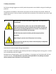
2. Safety Instructions Sun Pumps strongly suggests to carefully read this operation manual before using and installing its products. Any operation (installation, maintenance and repair) must be carried out by trained, skilled and qualified personnel. Failure to observe and follow the instructions of this manual may result in fatal electric shock. Disconnect the unit from the power supply before any maintenance is performed.
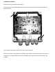
3. CM MP installation Remove the special inserts, shown below. Use two screws inserted through the holes underneath the inserts to mount the CM MP in a vertical position. Then replace the special inserts so the cover can be attached. The IP55 protection rating allows the CM MP to be installed in humid and dusty environments. However it is recommended to protect the CM MP from the direct exposure to weather and sunlight.
3.1 Electric Wiring 5 Input power line (LINE): • L1, L2 power line • GND ground Output power line (PUMP): • M1, M2 power line • GND ground Pump Signal: • S+ (red) • S- (white) Analog inputs (10 or 15 Vdc): Digital inputs (Pump start / stop): Digital outputs (relays): 1. AN1: 4-20 mA: sensor 1 2. AN2: 4-20 mA: sensor 2 3. AN3: 4-20 mA / 0-10 Vdc (settable by jumper C.C.): external set 4. AN4: 4-20 mA / 0-10 Vdc (settable by C.C.
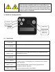
Carefully read the safety guidelines before installing the device. At the end of the installation, make sure no other objects are inside the CM MP or deposited on the electronic board. Tighten all 4 screws with the washers on the cover before powering up the device. Failure to properly ground the controller may result in electric shock or even death. 4. CM MP use and programming Scroll up Scroll down START pump ENTER STOP pump Menu exi t Alarms reset 4.
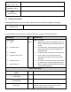
%f 25 50 75 100 %h XX XX XX XX XXXXXXXXXXXXXXX XXXXXXX h : XX m Menu ENT to access 4.2 Installer Parameters Pressing ENTER where you are in (Menu’ / ENT to access), the following MENU is displayed: MENU Instal. Param. Password required to enter (default 001) To exit the Menu level and return to INITIAL DISPLAY is enough to press STOP button. PARAMETER Control Mode: • MPPT DEF. MPPT • Constant Value • Fix Speed • Constant Value 2 Set • Fix Speed 2 Val.
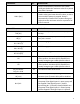
PARAMETER DEF. Min alarm value 0 XXX.X [bar] PARAMETER DEF. DESCRIPTION Pump is automatically restarted if the readen value goes below the maximum value for a period of at least 5 seconds. Minimum value allowed in the system. If the readen value goes lower than this value, an alarm occurs and the pumps is stopped. Pump is automatically restarted if the readen value goes higher than the minimum value for a period of at least 5 seconds. DESCRIPTION Freq. min.
Digital input 2 N.O. N.O./N.C. Digital input 3 N.O. N.O./N.C. Digital input 4 N.O. N.O./N.C. Dig.in.2/3 delay T = XX [s] 3 Change PASSWORD1 ENT By selecting N.A. (normally open) CM MP runs the pump if the digital input 2 is open; pump will be stopped if the digital input 2 is closed. By selecting N.C. (normally closed) CM MP runs the pump if the digital input 2 is closed; pump will be stopped if the digital input 2 is opened. By selecting N.A.
Periodic autorun 0 T = XX [h] AN1, AN2 function Independent XXXXXX Pump periodic autorun after XX hours of inactivity. Value 0 makes function disabled. Warning: review the advice in Chapter 1. Function logic for analog input AN1, AN2 (independent, lower value, higher value, difference 1-2). Zero correction for analog input 1 (4-20 mA) (20 mA x 20% = 4 mA). Offset input 1 [%] 20% Offset input 2 [%] 20% Zero correction for analog input 2 (4-20 mA) (20 mA x 20% = 4 mA).
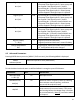
IGBT TRIP ALARM Electronics overload • Check possible causes for overload. ALARM MESSAGE ALARM DESCRIPTION MAX. VALUE ALARM Measured value has reached the maximum value accepted by the system. Measured value has reached the lowest value accepted by the system. • Check possible causes of reaching max value • Check the max alarm value setting. Communication between the CM MP and the pump has been interrupted.