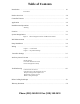
Table of Contents Introduction ………………………………………………………………………... 1.0 Precautions Product Overview …………………………………………………………………. 2.0 Controller Features ………………..………………………………………………. 2.1 Application ………………………………………………………………………... 2.2 Installation and Operations ………………………………………………………… 3.0 Warning Location …………………………………………………………………………… 3.1 System Design Basics ……………………………………………………………... 3.2 Figure 1: Well Measurements Solar Pump System Terms and Head Calculations ……………………………………………………………… 3.
1.0 Introduction Thank you for selecting a SunPumps SDS series solar pump system. The SDS series pump and PCA-30M1D series pump controller are the key components to high quality solar powered pumping systems. Their stand-alone, pollution free operation makes them an ideal solution for remote homes, irrigation projects, and wildlife and stock watering without violating the environment.
8. 9. 10. 11. Weather resistant enclosure with a hinged door. Rising clamp screw terminal blocks – no fork terminals required. Pre-adjusted pump configuration and power source selection. Remote switch interface – float switch or remote shutdown –Normally Open or Normally Closed, user selectable. 2.2 Application The only application the PCA 30M1D series controllers are designed for is the interface between a solar module array and SunPumps SDS series DC pumps.
3.2 System Design Basics (Read carefully before installation) 1. Use no larger than ½” drop pipe for SDS-D and SDS-T series pumps and ¾” drop pipe for SDSQ series pumps. Because of the low flow rates of the SDS series pumps, the water velocity is not fast enough to carry any sand and sediment to the surface. These small particles may settle inside the pump as well as the drop pipe causing pump damage. 2. If there is a known sand problem, a sand shroud or a screen is required.
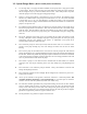
3.3 Well Measurements Before installing the pump measure the depth of the well and static water level. The static water level is the distance from the top of the well casing to the water level in the well. This information is necessary in determining the pump setting (See Figure 1).
3.4 Pump Installation 1. The well should be clean and disinfected before the pump is installed. You should always clean and develop a new well before installing the pump. 2. Write the pump and controller model number and serial number in the space provided on the last page in this Instruction Manual. This information will be needed when filling out the Warranty Card. And will aide in any troubleshooting which may be necessary. 3.
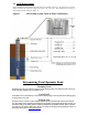
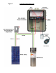
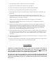
Figure 2 Controller Wiring Diagram
1. After mounting the controller, switch the controller to the OFF position. 2. Connect ground rod conductor to the controller chassis ground block. 3. Connect solar module frame ground conductor to controller chassis ground block. 4. Connect the green pump ground conductor to controller chassis ground block. 5. Connect pump motor leads to the corresponding “Pump” terminals on the controller. Red to LD+, and black to LD-. 6.
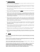
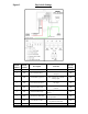
Figure 3 Dip Switch Settings Switch Switch Number Position 1 ON 2 Description 12-17 Volt Panel Direct Function Default Setting Sets Controller for a 12 to 17 volt input. OFF ON 24 Volt Battery System Sets Controller for a 24volt battery input. OFF 3 ON 24-34 Volt Panel Direct Sets Controller for a 24 to 34 volt input ON 4 OFF Remote Switch Logic Turns pump Off when terminals connect.
3.6 Controller Settings The PCA series controllers have several settings , see figure 3. Most features include system configuration adjustments, some of which are user selectable by a six position DIP-switch located on the face of the controller. Switch 1 is the 12 to 17 volt panel direct setting. With this switch on (UP), the controller is adjusted for a 12 to 17 volt solar module. Switch 2 is the 24 volt battery setting. With this switch on (UP), the controller is adjusted for a 24 volt battery system.
With switch number 4 in the ON position, the controller is configured to accommodate a Normally Closed (N.C.) float switch, pressure switch or remote toggle switch. In this configuration the controller will operate as follows: PUMP ON switch closed = water tank low = pump ON PUMP OFF switch open = water tank high = pump OFF Sensorless Low Water Cut-Off Circuit (LWC) The Low Water Cut-Off Circuit (LWC) turns the pump off any time the controller output power drops below a functional level.
Motor Speed Control Adjustment The purpose of this procedure is to adjust the output voltage of the controller and thus reduce the water flow of the pump. If tests have shown the pump will out produce the well capacity, then the controller “Speed Control” feature can be used to match the flow rate of the pump to the production of the well. 1. With the system installed and controller properly configured, allow the pump to run at full power at mid-day until the pump starts surging. 2.
4. If the fourth LED, labeled “Over Current” is on and blinking, the controller has exceeded its current limit and shut down. Turning the controller off then on again will reset this fault. If the controller continues to pull high current, it will turn itself off again. Check the pump for a short to ground using an ohm meter and call Sun Pumps for further assistance. 5. Check the fifth LED, labeled “Low Water Cut-Off”, this is the low water shutdown indicator.
5.0 Before Calling SunPumps BEFORE CALLING SUNPUMPS If at all possible when calling Sun Pumps for technical support there are a few things which will help to speed up the process and help us determine the cause of and solution to the system failure. The best way to get help is to call while you are physically at the location of your pump, have good sunlight, and have a multimeter and a screwdriver with you. Furthermore, please fill out the form below before calling.
6.0 Warranty Statement Warranty Statement SDS Series Submersible Pumps PCA Series Pump Controllers Limited Warranty – Twelve Months SunPumps warrants to the original consumer that its products shall be free from defects in material and workmanship under normal applications and service conditions for a period of twelve (12) months after the original date of purchase, but not to exceed eighteen (18) months from the date of manufacture.