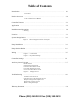
Table of Contents Introduction ………………………………………………………………………... 1.0 Precautions Product Overview …………………………………………………………………. 2.0 Table 1: Differences in Models Controller Features ………………..………………………………………………. 2.1 Application ………………………………………………………………………... 2.2 Installation and Operations ………………………………………………………… 3.0 Warning Location …………………………………………………………………………… 3.1 System Design Basics ……………………………………………………………... 3.
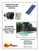
1.0 Introduction Thank you for selecting a SunPumps SCS series solar pump system. The SCS series pump and PCC series Sensorless Brushless DC - pump controller are the key components to high quality solar powered pumping systems. Their stand-alone, pollution free and low noise operation makes them an ideal solution for remote homes, irrigation projects, and wildlife and stock watering without violating the environment.
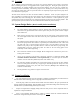
2.1 Controller Features 1. 2. 3. 4. 5. 6. 7. 8. 9. 10. 11. 12. 13. 14. 15. 16. Current boosting for matching the load requirements of the pump. Voltage regulation of the solar electric array at its maximum power point. (MPPT) Over-current protection via integrated electronic circuit breaker. Reverse polarity protection (10 amperes maximum) on the input terminals. Voltage and current limiting to pump motor. Transient protection and surge suppression.
3.1 Location As the majority of system installations vary greatly, only general comments can be made as to location. Prior to installing the system, it is suggested to make a system layout plan. During the system layout, take into consideration any potential shading of the solar electric modules, wire runs, wire size, conduit runs, trenching, controller accessibility, tank location, pump head etc.
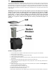
3.4 Pump Strainer Basket This pump has a basket strainer, sometimes called a “Hair and Lint Pot” located in the front section of the pump volute. Inside this chamber is a basket which must be kept clean of leaves and debris at all times. View the basket through the “See-Through Lid” to inspect for various accumulations of trash. Regardless of the length of time between filter cleaning, it is most important to visually inspect the basket at least once a week.
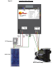
3.5 Wiring Prior to connecting any wires to the controller, be sure you have a system wiring diagram to use as a reference (see figure 2). Guessing at polarity and connection points is not worth the risk of potential product damage and/or personal injury. Ensure the wire sizes are of adequate diameter (gauge) to minimize voltage drop. Please refer to a DC voltage loss table or call your SunPumps dealer for assistance.
Figure 2 Controller Wiring Diagram
1. After mounting the controller, switch the controller to the OFF position. 2. If you are using a remote switch, like a float switch, set dip switch 1 to the correct position for the type of switch being used. (“Normally Open” or “Normally Closed”.) If you are not using a remote switch leave switch 1 off. 3. Verify all remaining dip switches are off at this time. 4. Connect ground rod conductor to the controller chassis ground block. 5.
Figure 3 Dip Switch Settings Switch Switch Number Position 1 Description Function Default Setting OFF Remote Switch Logic Turns pump off when terminals connect. OFF 1 ON Remote Switch Logic Turns Pump on when terminals connect. OFF 2 OFF Low Water Cutoff Logic Turns pump off when terminals connect. OFF 2 ON Low Water Cutoff Logic Turns pump on when terminals connect.
3.6 Controller Settings The PCC series controllers have several settings (see figure 3). Most features include system configuration adjustments, some of which are user selectable by an eight position DIP-switch located on the face of the controller. Switch 1 is the Remote Switch Logic. With this switch off (down), terminals “RS+” and “GND” must be connected to turn the controller off. With this switch on (up), terminals “RS+” and “GND” must be connected to turn the controller on.
Remote Switch The Remote Switch interface can serve as an automatic system shutdown when used with a water storage tank mounted float switch, a pressure switch or it can also serve as a manual system shutdown with a remote system ON/OFF toggle switch. The remote logic circuit allows the use of standard “Pump-Up or Pump Down” float switches. Please refer to the following operation scenarios for configuration options.
Output Power Limit Circuit (Motor Speed Control) The Output Power Limit Control circuit is used to control the speed of the pump motor and thus the flow rate of the pump. It is primarily used for low producing wells where the pump output is matched to the production rate of the well. However it can also be used any time specific flow rates are required. Output Power Limit Adjustment The purpose of this procedure is to adjust the output power of the controller and thus reduce the water flow of the pump.
Figure 4 Display Screens NOTE: Dip switch 7 will freeze the display on the current screen. If the system is powered up with switch 7 on, the display will only show the SUNPUMPS, INC screen. Turn off switch 7 to unfreeze the display.
4.0 Troubleshooting Sun Pumps, Inc. is dedicated to its customers and will gladly help you trouble shoot any problems with your system. However, especially during the busy summer pumping season, we may not be able to help you right away. Using this trouble shooting guide as your first resource when your system is not working properly can save you valuable time in getting your system fully functional.
displays “GF FUSE OPEN” the ground fault fuse has been blown. Check your system for ground loops and replace the fuse with a 500 VDC 1A rated fuse. If this does not solve the issue, contact Sun Pumps for further assistance. 7. Check for proper dip switch settings on your controller. Switches 5, 6, and 8 must be in the off position for proper operation. 8. Check for proper controller input voltage. A quick look at the controller display will verify the array voltage.
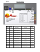
BEFORE CALLING SUNPUMPS If at all possible when calling Sun Pumps for technical support there are a few things which will help to speed up the process and help us determine the cause of and solution to the system failure. The best way to get help is to call while you are physically at the location of your pump, have good sunlight, and have a multimeter and a screwdriver with you. Furthermore, please fill out the form below before calling.
Warranty Statement SCP Series Booster Pumps PCC Series Pump Controllers Limited Warranty – Twenty Four Months SunPumps warrants to the original consumer that its products shall be free from defects in material and workmanship under normal applications and service conditions for a period of twenty (24) months after the original date of purchase, but not to exceed eighteen (30) months from the date of manufacture.