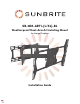
SB-WM-ART1-[L/XL]-BL Weatherproof Dual-Arm Articulating Mount for Large Displays Installation Guide
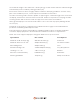
The maximum weight of this wall mount is 150 lbs (68 kg). Use with heavier than the maximum weight indicated may result in instability causing possible injury. Ensure these instructions are thoroughly understood before attempting installation. If unsure of any part of the installation process, contact a professional installer for assistance. The wall or mounting surface must be capable of supporting the combined weight of the mount and the display; otherwise the structure must be reinforced.
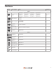
Hardware Image Description Item Quantity BAG 1 TV Mounting Bolts (A) M4×10 (E) M5×10 (I) M6×10 (M) M8×10 (B) M4×20 (F) M5×20 (J) M6×20 (N) M8×20 (C) M4×30 (G) M5×30 (K) M6×30 (O) M8×30 (D) M4×40 (H) M5×40 (L) M6×40 (P) M8×40 Flat Washer (Q) M5 (R) M8 16 8 Nylon Spacer (S) M4/M5 (T) M6/M8 8 8 Square Washer (U) 36.2×2.
Installation Layout and Drilling Determine general location of the display. Use a level to tape the template flat and level on the wall. For wood walls, use a stud finder to find the nearest wall studs. Mark their location, and align the template’s slots with the centers of the stud markings. Pro Tip: Fold the template corners up to catch debris as you drill. Caution: Before drilling, verify the concrete is at least 1-3/8” thick.
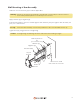
Wall Mounting of Arm Assembly Hammer concrete anchors (V) into wall as applicable. Warning: If anchors are going to be applied to a plastered concrete wall, the anchor must be recessed beyond the plaster to reside fully in the concrete. Apply washers (Z) to lag bolts (X). Place Arm Assembly in position. Thread lag bolts with washers (X+Z) through the Arm Assembly into pilot joles / wall anchors. Pro Tip: Orient the Arm Assembly so that its Keyed Notches side of the Head Mount are up.
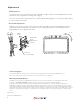
Assemble TV Bracket Lay the TV flat on a soft, flat, surface and locate the four VESA mounting bracket holes. Determine the VESA pattern and prepare the TV bracket and adapters accordingly. Medium Displays (Up to VESA 400×400) Assemble the four SunBrite adapter arms on the TV adapter plate using 8 bolts (AA). Test the TV mounting bolts (A–P) and find the diameter that fits the VESA mounting holes. Fasten the plate using the shortest screws possible.
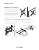
Attach TV to Arm Assembly Caution: Only lift the TV with two persons. These instructions are the same for all TV sizes. Pull the head of the arm assembly out from the wall and tilt the Head Mount down as much as possible. This makes it easy to mount the TV. On the TV, insert two bolts (BB) into the top two holes of the TV adapter plate.
Adjustments Tilt Adjustment Loosen the tilt levers on the head of the arm assembly enough to allow controlled adjustment. Set the desired tilt, then re-tighten the locking levers. (Fig.11) Once the tilt levers are locked, their position can be adjusted by pulling out on each lever and rotating it to a less obtrusive position. Horizontal Adjustment Slightly loosen the two screws on the head of the arm assembly using the provided Hex key (Fig.11).