
Installation Instructions
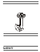


SB-CM32A12 Installation Ins truction s
6
INSTALLATION
WARNING: Failure to provide adequat e structural strength
for this component can result in serious personal injury or
damage to equipment! It is the installer’s responsibility to
make sure the structure to which this component is attached
can sup port five t imes t he combi ned wei ght of al l eq uip ment.
Reinforce the structure as required before installing the
component.
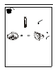
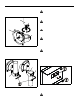
1. Using cei l in g plat e (C) as a templ at e, mark l ocati ons of t wo
pilot holes (See Figure 1). Ensure the following:
• Use OPPOSITE holes in plate (C), and
• Marks are in the center of wood joist.
NOTE: Drywall not shown for clarity.
Figure 1
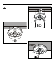
2. Drill 1/4" diamet er pilot hol es into woo d joist. (See Figure 2)
Ensure pilot holes are straight.
Figure 2
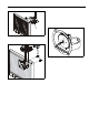
3. Using 9/16" socket wrench, loosely install two (minimum)
Grade 2 (not included) 3 /8" x 2 -1/2" lag sc rews t hrough 3/ 8"
washers (E), ceiling plate (C), into wood joist (See Figure 2).
Do not tighten plate (C) against ceiling at this time to
accommodate cable insta llation.
NOTE: Two additional washers are provided.
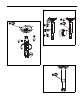
4. Route cables through channel in ceiling plate (C). (See
Figure 3)
Figure 3
5. Tighten lag screws. (See Figure 2)
1
x 2
(C)
3
x 2
2
x 2
5
(C)
(E) x 2
4
(C)