
Installation Instructions


Installation Instructions SB-CM32A12
7
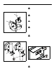
ADJUSTABLE LENGTH EXTENSION
COLUMN
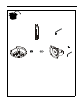
1. Install adjustable column (A) into plate. (See Figure 4)
Securel y tight en co lumn.
• Ensure column ( A ) engages four full thr eads into plate.
• Ensure cable access opening is rotated to desired
position (optional in stallation, column (A)).
Figure 4
2. Secure col umn (A) by tight ening set screw (D) in plat e using
3/16" hex key (B). (See Figure 4)
NOTE: Two adjustment holes provided in interior (fixed)
colu mn . Either adjustmen t hole can be u sed to provide
1" (25mm) adjustment increments.
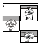
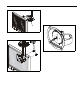
3. (Optional) Remove button head cap screw and supporting
washers from lower adjustment hole if an additional 1"
(25mm) adjustment increment is desired. (See Figure 5)
4. (Optional) Replace button head cap screw and supporting
washers int o upper adjustment hol e to provide an ad ditional
1" (25mm) adjustment increment. (See Figure 5)
Figure 5
5. Adjust column (A) to desired length, then rotate and lock
into position. (See Figure 5)
NOTE: Any locking slot can be used to provide 1" (25mm)
adjustment increments.
6. Tighten adjustment screw using 3/16" hex key (B). (See
Figure 5)
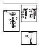
7. Tighten set screws on back of pipe using 3/16" key (B).
(See Figure 6)
NOTE: Optional installation similar; not shown.
Figure 6
4 x
1
1
4 x
(A)
2
(D)
(C)
4
6
5
(A)
3
7
x 2
(rear view)