
Installation Instructions


SB-CM32A12 Installation Ins truction s
8
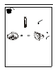
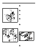
Head Assembly Installation
1. Thread head assembly (F) o nto adjust ment col umn (A) until
hand tight. (See Figure 7)
2. Adjus t head assembl y (F) posit ion until Cen tris cup is facing
the desired position of the display. (See Figure 7)
Figure 7
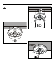
3. When head assembly (F) is properly positioned, secure
head assembly (F) to adjustment column (A) by installing
and tight eni ng 5/ 16-18 x 3/ 8" s et screw ( G) using 5/ 32" hex
key (H). (See Figure 8)
NOTE: If moun t is being used to couple two pipes , use both se t
screws when securing head assembly (F) to pipes.
Figure 8
Display Installation
WARNING: IMPROPER INSTALLATION CAN LEAD TO
EQUIPMENT FALLING CAUSING SERIOUS PERSONAL
INJURY AND DAMAGE TO EQUIPMENT! DO NOT
substitute hardware. Use only hardware supplied by
manufacturer!
WARNING: IMPROPER INSTALLATION CAN LEAD TO
ELECTRIC SHOCK OR DAMAGE TO EQUIPMENT! Screw
lengt h must no t exce ed the dept h of t hreaded mounti ng insert
in display.
WARNING: OVERTIGHTENING OF SCREWS CAN
DAMAGE PARTS AND LEAD TO SERIOUS PERSONAL
INJURY AND DAMAGE TO EQUIPMENT! DO NOT over
tight en screws when i nstal ling interface bracke t.
WARNING: IMPROPER INSTALLATION CAN LEAD TO
DISPLAY FALLING CAUSING SERIOUS PERSONAL
INJURY OR DAMAGE TO EQUIPMENT! Using screws of
improper size may damage your display! Proper screws will
easily and completely thread into displ ay mounting holes.
Ensure that screws are not too long.
WARNING: IMPROPER INSTALLATION CAN LEAD TO
DISPLAY FALLING CAUSING SERIOUS PERSONAL
INJURY OR DAMAGE TO EQUIPMENT! Inadequate thread
engagement in display may cause display to fall! Back out
screws ONLY as necessary to allow installation of Centris
cup!
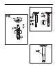
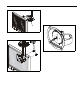
1. Loosen the top two mounting screws on the back of the
disp lay to prutrude 1/8" an d remove t he botto m two scre ws.
(See Figure 9)
Figure 9
2. Align two screws in display back with upper teardrop
mounting holes in mounting plate and lower display until
screws ar e seated in lower area of teardrop mounting hole s.
(See Figure 10)
CAUTION: Do not let go of the telev is ion at this point. Hold
the television in place while proceeding to the next step!
1
(A)
Centris Cup
(F)
3
(G) x 1
(F)
3
(F)
(G) x 1
(H)
loosen
remove
to 1/8"
1
1