SB-WM-ART1-M-BL Weatherproof Universal Single-Arm Articulating Mount for Medium Displays INSTALLATION MANUAL
maximum weight of this wall mount is 90 lbs (41 kg). Use with heavier than the WARNING The maximum weight indicated may result in instability causing possible injury. Ensure these instructions are thoroughly understood before attempting installation. If unsure of any part of the installation process, contact a professional installer for assistance. The wall or mounting surface must be capable of supporting the combined weight of the mount and the display; otherwise the structure must be reinforced.
INSTALLATION Layout and Drilling 1. Determine general location of the display. 2. Use a stud finder to find the nearest wall stud if applicable and mark their location. 3. Tape template flat and level to wall surface, aligning the template’s slots with the stud markings on the wall. NOTE: Use of a bead level is recommended. NOTE: Template corners fold up to catch debris. 4. Use a pen or pointed object to mark bore locations.
Assemble TV Bracket Lay the TV flat on a soft, flat surface and locate the four VESA mounting bracket holes, then determine the VESA pattern and prepare the TV bracket and adapters accordingly. Small Displays (Up to VESA 200x200) Figure 2A 1. (Fig.2A) Use only the TV adapter plate. 2. Test the TV mounting bolts (A-M) and find the diameter that fits the VESA mounting holes. (Fig.2B) Figure 2B 200 100 75 3. Attempt to fasten the plate using the shortest possible screws.
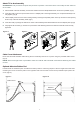
Attach TV to Arm Assembly ATTENTION: This procedure requires two persons to perform. The instructions in this step are the same for all TV sizes. 1. Pull the head of the arm assembly out from the wall and move the tilt adjustment down as much as possible. (Fig.5) 2. Insert two bolts (Y) into the top two holes of the TV adapter plate. Leave approximately 1/4” of exposed thread (do not fully tighten). (Fig.6) 3.
Adjustments Tilt Adjustment Loosen the tilt levers on the head of the arm assembly enough to allow controlled adjustment. Set the desired tilt, then re-tighten the locking levers. (Fig.11) Once the tilt levers are locked, their position can be adjusted by pulling out on each lever and rotating it to a less obtrusive position. Horizontal Adjustment Slightly loosen the two screws on the head of the arm assembly using the provided Hex key (Fig.11).
170315-0814