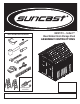
BMS7791 – Sutton™ Blow Molded Resin Storage Shed ASSEMBLY INSTRUCTIONS Tools needed for installation INCLUDED IN KIT XX Easy Bolt Easy Driver 010210410 Quality Control Number: © 2015 Suncast Corporation, Batavia, IL Assembled exterior dimensions 7' 4 1/2" W. x 7' 2 1/2 " D. x 8' 6" H.
Before You Begin... • Consult your local authorities for any permits required to construct shed. Prior to the construction of your shed, check with the local building code official to review any required permits or building limitations. • A level and sturdy foundation is required before shed construction can begin. Review the site preparation information within the manual before beginning assembly. • Read instructions thoroughly prior to assembly.
Shed Safety and Care • Hot items, such as recently used grills, blowtorches, etc., must not be stored in the shed. • Heavy articles should not be leaned against the walls, as this may cause panel distortion and permanent damage. • Keep roof clean of snow and leaves. • The shed walls and roof sections have a textured exterior, much like vinyl home siding. Over time, dust may accumulate in the texture. When combined with moisture, this could encourage the growth of moss or mold on the shed.
IMPORTANT PEN ALL BOXES FIRST AND NEATLY LAYOUT PARTS. SMALL PARTS MAY BE CONTAINED O IN EACH BOX. PLEASE REFERENCE THE PARTS LIST WITHIN THIS MANUAL TO VERIFY ALL PARTS ARE PRESENT. COMPLETE SITE PREPARATION AND FOUNDATION CONSTRUCTION BEFORE UNPACKING ALL PARTS.
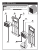
Parts - BMS7791 Doors IMPORTANT OPEN ALL BOXES FIRST AND NEATLY LAYOUT PARTS. SMALL PARTS MAY BE CONTAINED IN EACH BOX. PLEASE REFERENCE THE PARTS LIST WITHIN THIS MANUAL TO VERIFY ALL PARTS ARE PRESENT. COMPLETE SITE PREPARATION AND FOUNDATION CONSTRUCTION BEFORE UNPACKING ALL PARTS.
Parts - BMS7791 Headers IMPORTANT OPEN ALL BOXES FIRST AND NEATLY LAYOUT PARTS. SMALL PARTS MAY BE CONTAINED IN EACH BOX. PLEASE REFERENCE THE PARTS LIST WITHIN THIS MANUAL TO VERIFY ALL PARTS ARE PRESENT. COMPLETE SITE PREPARATION AND FOUNDATION CONSTRUCTION BEFORE UNPACKING ALL PARTS.
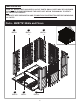
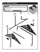
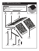
Parts - BMS7791 Roof and Truss IMPORTANT OPEN ALL BOXES FIRST AND NEATLY LAYOUT PARTS. SMALL PARTS MAY BE CONTAINED IN EACH BOX. PLEASE REFERENCE THE PARTS LIST WITHIN THIS MANUAL TO VERIFY ALL PARTS ARE PRESENT. COMPLETE SITE PREPARATION AND FOUNDATION CONSTRUCTION BEFORE UNPACKING ALL PARTS.
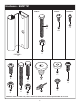
Hardware - BMS7791 0480374 0480375 0480302A LL HH KK x2 x70 x105 JJ FF x2 OMP000002 – x6 0480337 0480340 0480322 0480346 B YY x11 MM GG II x6 JJ x6 x6 ZZ HH x4 AAA x28 x2 XX JJ x4 x6 Hardware shown at actual size (*Unless otherwise noted.) Extra hardware provided. Not all are used.
Door Handle Kit - BMS7791 0440647B OO PP 0630891A 0630895 – x2 NN 0630624 – x2 QQ 0670147 Hardware 0480306B – RR CCC x5 x7 Hardware shown at actual size (*Unless otherwise noted.) Extra hardware provided. Not all are used.
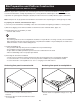
Site Preparation and Platform Construction Materials NOT supplied with BMS7791 Shed Kit ote: Site preparation is required for this shed. Placing the shed on a constructed foundation is required. Without N a constructed foundation, settling will probably occur, causing distortion and damage to the shed. Suncast is not responsible for replacing parts damaged or property lost due to incorrect assembly. Warranty requires foundation.
Site Preparation and Platform Construction (continued) Materials NOT supplied with BMS7791 Shed Kit Wood platform critical spacing 1 12 4 " (APPROXIMATE) 3 42 4 " 29" 1 15 4 " 1 15 4 " 29" 1 84" 1 85 4 " 3 94" FRONT 84" • Check all critical spacing measurements.
Door Pre-Assembly Peel film from both sides of window (S). 1 Note: One side of film will say "THIS SIDE OUT." Make sure this side faces out when installing window. S THIS 2 SIDE OUT Stand left door (I) vertically. In this order, layer into door channel the window gasket (TT), door window (S), and door window frame (Q). Through the back of door, secure layers with ten screws (LL). Start with four corner screws and finish with remaining screws. DO NOT over tighten screws.
Door Pre-Assembly (continued) 3 Secure center of window with one washer head screw (ZZ) and sealing washer (YY). DO NOT over tighten screws. ZZ x1 Repeat on Steps 1-3 for right door (H). Note: At least two people are needed during assembly. YY x1 I ZZ x1 1 x1 YY 2 1 I LL x4 1 5 4 LL x4 I W W x4 2 2 x4 At top interior side of left door (I), attach D-ring slide bolt (W) with four screws (LL) through provided holes.
Header Pre-Assembly 6 7 V R 1 VV 1 1 J KK x2 LL x4 J 2 2 Slide roof ridge beam bracket (V) under tabs on inside peak of front header (J) and secure with two screws (KK). DO NOT over tighten screws. Place fiberglass vent screen (VV) and header vent (R) into front opening in front header (J). Secure through back of header with four screws (LL). DO NOT over tighten screws. 8 Lay header (J) on ground with lettering side facing up.
Truss Pre-Assembly 9 10 AA AA 1 1 AA AA CC Y x2 II 1 x2 x2 2 HH x2 3 x2 JJ 3 JJ x2 Attach truss bracket (Y) to end of one truss leg (AA) with 1" hex head cap screw (II) and nut (JJ). Attach truss cross beam (CC) to two truss legs (AA) using two hex head cap screws (HH) and two nuts (JJ). Stand truss and check cross beam is level. Repeat for second truss leg (AA). 12 11 AA AA 1 JJ 1 Z Z JJ HH HH 3 3 2 2 Place window truss tie down (Z) at end of right truss leg (AA).
Shed Assembly/Walls 13 Critical: When installing corners, flex corner hinges back and forth several times. This will help provide a square corner and ensure proper fit of remaining panels. Important: DO NOT flex in reverse position, as this can crack the panel. 14 15 x6 LL C B 1 1 A 2 2 A Push front floor (A) and rear floor (B) panels together and secure with six screws (LL). Align tab on bottom right side of left front (C) with slot on front floor (A).
Shed Assembly/Walls (continued) 17 C 1 1 16 C 2 2 Tip left front (C) outward slightly and bend corner hinge. Tip left front (C) back to vertical position and align lower tabs on right side with slots in floor. Note: You will hear a snap when tab is fully engaged. 18 Before proceeding, make sure corner is square (top view) where it meets the floor and that panel is flush (side view) with floor. If not, repeat Steps 15-17 until square and flush.
Shed Assembly/Walls (continued) 19 Align tabs on bottom of side panel (D) with slots along front and rear floors. Lower panel into slots and lock in place by sliding panel toward front corner. D Note: Use a rubber mallet to “push” side panel (D) into locked position. 2 1 ecure side panel with four easy bolts (GG), working S from floor to roof. DO NOT use torque wrench. Use easy bolt easy driver (XX) and hand tighten. Easy bolt head will be flush when fully seated. DO NOT over tighten easy bolts.
Shed Assembly/Walls (continued) 21 E D E D Hardware Necessary G Repeat Steps 15-20 for remaining panels.
Shed Assembly/Headers and Truss 22 23 K 1 1 J 1 1 x4 2 KK 2 Place front header (J) over door opening and fit two protruding support legs into pockets molded in front corners. Secure front header using two screws (KK) in each front corner. 2 KK x8 Place rear header (K) over back walls and fit four protruding support legs into pockets molded in back walls. Secure rear header using eight screws (KK).
Shed Assembly/Headers and Truss (continued) 27 26 U 1 U JJ HH 3 2 2 HH 3 JJ Raise ridge beam (U) up and into rear roof ridge beam bracket. Secure with one 2" hex head cap screw (HH) and one nut (JJ). Slide ridge beam (U) into front roof ridge beam bracket. Secure with one 2" hex head cap screw (HH) and one nut (JJ). Note: Alignment of ridge beam to bracket may require header panels to be pushed inwards or outwards slightly as ridge beam is slid into place.
Shed Assembly/Roof Before proceeding, locate and identify channels on interior side of right roof (L) and left roof (M). Locate three underside tabs contained within each channel. 30 Before proceeding, locate and identify six front header tabs and six rear header tabs. L 1 1 J 1 X3 Lay right roof (L) directly over three tabs on right side of front header (J). With right roof channel seated over/on header tabs, check alignment in all three spots.
Shed Assembly/Roof (continued) Slide right roof (L) down towards the outside of shed. You will hear a "snap" when engaged. 31 L x3 Press edge of right roof (L) into channel on truss leg (AA).
Shed Assembly/Roof (continued) 33 M M 4 3 2 L End View Front View 1 Repeat steps 30-32 for remaining roof panels. Install panels in the order shown. 34 35 D G 1 11 3 KK x4 1 2 2 Pull down each lower corner of roof from outside. From inside shed, attach tabs on panel (D) and right front (G) corner to roof panel with four screws (KK). KK x6 Secure roof to truss using six screws (KK). Each screw will attach at a corresponding screw boss on the roof.
Shed Assembly/Roof (continued) 36 37 1 1 1 1 WW 1 KK x3 3 LL 2 4 Raise roof support (WW) into position against roof. Slide roof support (WW) into front header. Secure roof support (WW) to underside of truss leg with one screw (LL). Secure roof support (WW) to roof using three screws (KK). 38 Repeat Steps 34-37 to secure remaining roof panels.
Shed Assembly/Roof (continued) Push down the roof from outside. From inside shed, secure roof panels together along ridge of roof using six rubber washers (YY) and six sealing screws (AAA). 39 Note: For clarity, illustration is shown with front header, right front corner, and window panel removed.
Shed Assembly/Doors Stand right door (H) upright with three hinge mounts facing right. Slide one metal hinge plate (FF) up onto each hinge mount. Rotate hinge plates to outside of door. Snap metal hinge plate into place by pushing towards door. 40 H x3 FF x3 2 Rotate metal hinge plates to open position. Slide one metal hinge plate over each hinge receptacle on inside of right front panel. 41 Note: For clarity, illustration is shown with roof removed.
Shed Assembly/Doors (continued) Secure each metal hinge plate with one screw (MM) and one nut (JJ). 42 Repeat Steps 40-42 for left door (I). Note: For clarity, illustration is shown with roof removed. 2 1 1 JJ x3 MM x3 43 Insert screw stems, on left and right handle plates (OO) and (QQ), through the pre-drilled holes in doors. While holding plates in place on exterior of door, secure each with two washers (RR) and two machine screws (CCC).
Shed Assembly/Doors (continued) 44 From the outside of doors, insert door handles (NN) through handle plate holes. On inside of doors, place spacers (PP) on each door handle, and secure each with one machine screw (CCC). NN x2 1 1 2 PP x2 2 x2 CCC x2 3 Complete.
Warranty Warranty SUNCAST® Building, Shed and Gazebo Ten Year Limited Warranty Your SUNCAST® Building, Shed or Gazebo has a TEN YEAR LIMITED WARRANTY against product failure resulting from defects in manufacturing or materials. The warranty period starts on the delivery date. Incidental and consequential damages are not covered. Warranty Claims To file a warranty claim contact the manufacturer, SUNCAST® CORPORATION, 701 North Kirk Road, Batavia, Illinois, 60510. Call toll free (800) 846-2345 or visit www.