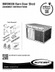
BMS9000 Barn Door Shed ASSEMBLY INSTRUCTIONS = Brilliant 3 { by Design” © i Els Chic Tools Required Er Scan OR Code for product assembly video. I; _— Cast. Smart.
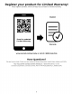
Register your product for Limited Warranty! Must register product within 90 days of purchase for limited warranty Register Scan for updated Limited Warranty Warranty or call US 1 (800) 846-2345 Have Questions? We are here to help. Check out our resource library along with helpful tips, videos and FAQ's. You may call the Contact Center directly at: 1 (800) 846-2345 or write Sun cast Corporation, Contact Center, 701 N.
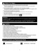
Before You Begin... * Consult your local authorities for any permits required to construct shed. Prior to the construction of your shed, check with the local building code official to review any required permits or building limitations. * A level and sturdy foundation is required before shed construction can begin. Site preparation information is available on pages 11-12. A foundation that differs from the suggestions within this manual could prevent proper assembly and may damage parts. .
Care Instructions Assembly Day Tips . Hot items, such as recently used grills, blowtorches, etc., must not be stored in the shed. Heavy articles should not be leaned against the walls, as this may cause panel distortion and permanent damage. Keep roof clean of snow and leaves. Your product is made of materials that will withstand outdoor use. Exposure to the elements {such as dust, plant and animal life, moisture and sunlight) encourages moss, algae, and mold to grow on outdoor items.
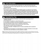
Walls and Floors IMPORTANT CONSTRUCTION BEFORE UNPACKING ALL PARTS, OPEN ALL BOXES FIRST AND NEATLY LAYOUT PARTS. SMALL PARTS MAY BE CONTAINED IN EACH BOX. PLEASE REFERENCE THE PARTS LIST WITHIN THIS MANUAL TO VERIFY ALL PARTS ARE PRESENT.
Sliding Doors IMPORTANT 1F FOUNDATION 18 REQUIRED, COMPLETE SITE PREPARATION AND FOUNDATION CONSTRUCTION BEFORE UNPACKING ALL PARTS, OPEN ALL BOXES FIRST AND NEATLY LAYOUT PARTS. SMALL PARTS MAY BE CONTAINED IN EACH BOX. PLEASE REFERENCE THE PARTS LIST WITHIN THIS MANUAL TO VERIFY ALL PARTS ARE PRESENT.
Roof Headers -Windows Door Track IMPORTANT iF FOUNDATION IS REQUIRED, COMPLETE SITE PREPARATION AND FOUNDATION CONSTRUCTION BEFORE UNPACKING ALL PARTS, OPEN ALL BOXES FIRST AND NEATLY LAYOUT PARTS. SMALL PARTS MAY BE CONTAINED IN EACH BOX. PLEASE REFERENCE THE PARTS LIST WITHIN THIS MANUAL TO VERIFY ALL PARTS ARE PRESENT.
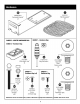
Steel Frame IMPORTANT 1F FOUNDATION 18 REQUIRED, COMPLETE SITE PREPARATION AND FOUNDATION CONSTRUCTION BEFORE UNPACKING ALL PARTS, OPEN ALL BOXES FIRST AND NEATLY LAYOUT PARTS. SMALL PARTS MAY BE CONTAINED IN EACH BOX. PLEASE REFERENCE THE PARTS LIST WITHIN THIS MANUAL TO VERIFY ALL PARTS ARE PRESENT. 1MRGO5006 Truss leg u 7 0 1MRGO1023 19" Ridge beam MPG0O023 Support bracket x12 TMRGO4004 Short wall adapter x2 1MRGO1022 o ] 87" Ridge beam 1MRG02003 69.
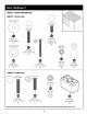
Hardware 0 0441007 Window gasket* OMP0O00047 Door guide bracket” x3 0480533 —MASTER HARDWARE BAG | 0480517 — Hardware Bag 0480513 Hardware Bag 0102666 010210410 0102188Ng Wall adapter cap* Easy bolt driver” Easy Bolt x4 Color: Passive white x5 0480377 0480516 Hardware Bag (x4) Hardware Bag 06832505 $s & Lock-Nut x30 0102188N6 0632504 0630821 . 0630183 Easy Lott 1/4790 3 #10x.625 #x.
Door Hardware 1 0480514 — Hardware Bag 0631773 1/4" Flat washer x11 0480534 ~ MASTER HARDWARE BAG 0632497 75" Carriage bolt x3 | —— (632496 25-20 x 1.25" Bolt x6 0631148 0631011 0632130 1747-90 0510087 3/8" Flat washer Screw Lock-nut Nylon spacer 0480515 ~ Hardware Bag ZN © 0631148 Lock-nut x10 0631456 0631116 0102748 25-20 x 1.5" Bolt 25-20 x 1" Hex bolt Door bumper x8 x2 x2 Hardware shown at actual size (*unless otherwise noted). Extra hardware provided. Not all are used.
Door Hardware 2 0102726 Grooved door OMPO00048 track wheel® Door hanger bracket” x2 x2 NINCOMPOOP" Latch catch plate 010272210 Door handle® Hardware shown at actual size {*unless otherwise noted}. Extra hardware provided. Not all are used.
Site Preparation and Platform Construction Materials NOT supplied with Shed Kit Important: » Site preparation is required for this shed. Placing the shed on a constructed square, flat and elev foundation is required. Without a constructed square, flat and level foundation, settling will probably occur, causing distortion and damage to the shed. Sun cast is not responsible for replacing parts damaged or property lost due to incorrect assembly.
Site Preparation and Platform Construction (continued) Materials NOT supplied with Shed Kit Wood platform critical spacing » Check all critical spacing measurements carefully. 1812 a 12.38” ¥ a8” i 129” 1314" mur B58" = Front a 73/87 315/18" 353/4" 33 6/8 3778 pa 4 13/167 [= 130" i. Wood platform materials list Item Qty Size .75" .75" 127" » Please note, 2 x 6 dimensional lumber is actually 1/2" smaller than noted sizes. Dimensions given presume standard 1.5" x 5.5" actual size lumber.
Place edge of middle floor panel {B} onto right floor panel (A} and secure with seven screws (JJ). Be sure the door guide brackets are facing the front of the foundation (front of foundation indicated earlier in these instructions). Note: Lay floor panels into position on foundation as they are assembled. 14 Stand left floor panel (D) horizontally on edge. On the underside of left floor panel (D), have a second person install a door guide bracket (GQ) and secure with three screws (JJ).
Door Pr-Assembly (continued) N= X On the inside of left door panel (8), install washers (TT), white nylon spacers (AAA), door latch {CCC and screws (XX) through mounting holes. On the outside of door panel (8}, place door handle (BBB) over screws (XX). Tighten the S Crews securely. Side View 7 To assemble door hanger, place bolt (VV} through top hole in door hanger bracket (RR) and install washer (UU), black nylon spacer (AAA), grooved door track wheel (QQ) and larger washer (TT). Secure with lockout (ZZ).
Door Pr-Assembly (continued) ged Lay door on a flat surface with show side face down. Align holes in L-bracket {I} with holes at top of door panel Overlap left and right door panels (8, T) and secure with assembly (8, T) and attach L-bracket {I} with four screws (MM). four white easy bolts (OO) using provided easy bolt driver {NN}. Listen for 3-4 clicks to indicate easy bolts are fully tightened. Repeat for remaining L-bracket {} at bottom of door panel assembly (1, 8).
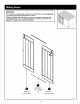
Header Pr-Assembly Place left side header (R) face down on flat surface. Starting at the top-center of window, press one end of gasket (i) into the channel and working around the window. Trim any excess gasket with scissors. Repeat gasket installation for remaining right side header {P), front right header (K) and front left header {J}. Note: Do not stretch gasket when installing.
Header Pr-Assembly (WW). Secure with 40 screws (MM). ( Place front left header (J) face down on a flat surface and install front windows place edge of right front header (K) into slot on edge of left front still face down on a flat surface, header (J). Make sure bottom edges of both headers are flush. Secure headers together with five screws (MM).
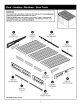
Header Pr-Assembly (continued) Place 31" header beams (AA) on left and right channel and 48" header beams (BB) on middle channel above and below the window openings of front left and right headers {J, K). Secure header beams (AA, BB) at top of header with twelve screws (MM) as shown. Secure header beams (AA, BB) at bottom of header with ten screws (MM) as shown. IMPORTANT: Make sure te install screws into exact locations only as shown (not all screw holes are used at this point in assembly).
Header Pr-Assembly (continued) With header assembly laid on a flat surface, nest door tracks {O) into pockets on outside of header assembly. Secure door tracks {O} with eight carriage bolts (DDD} and lockouts (FF. With right rear header (M} laying on a flat surface, place the right edge of the left rear header (1) info slot on edge of right rear header (M). Make sure bottom edges of both headers are flush. Secure headers together with three screws (MM).
Header Pr-Assembly (continued) With right and left assembled rear header beams (M, T) laying on a flat surface, place two 31" header bairns (AA) at each end and one 48" header beam in the center into channels. Secure header beams (AA, BB) with 12 screws (MM) as shown. IMPORTANT: Make sure to install screws into slots only as shown {not all screw holes are used at this point in assembly) Front Panel Pr-Assembly With front panel (H) face down on a protected surface, install the 89.
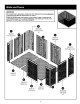
Align tab on bottom right side of left front corer (F) with front slot on left floor {D). Lower panel into slot and lock in place by sliding panel toward left edge of floor. Note: Use a rubber mallet to “push” left front T comer (Fl into locked position. To help prevent damage from mallet, pace a scrap piece of wood on the panel being struck by mallet, This will help distribute the force throughout the panel, minimizing the risk of damage. Tip left front corner (F} outward slightly and bend corner hinge.
Before proceeding, make sure corner is square {top view) where it meets the floor and that panel is flush {side view) with floor. if not, repeat Steps 19-21 until square and flush. T fos view Side view Hoe Align tabs on bottom of side panel (N) with slots along side of left floor {D). Lower side panel (N} into slots and lock in place by sliding left side panel (N) toward front left corner (F). Be sure all tabs are fully inserted into slots before sliding to lock.
X6 Place left and right {J, K} front header assembly over door opening and fit the five protruding support tabs into pockets in front left corner (F), front right corner {C} and front panel (H). Secure front header with eight screws (MM). Place left rear {T) and right rear {M) header assembly over back left corner (C), back panels {G) and back right corner and fit the eight protruding tabs into pockets provided. Secure rear header with 12 screws (MM).
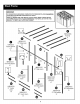
TIP: Have a second person hold wall from inside. Place left side header {R) into left front header (J) and aver left grant corner (F), side panel {N}, back left corner (C) and rear left header {T). Insert the protrusion at the back of left header (R} into the slot in the rear header (C} and press down on left header (R) to secure in position, Insert the two protrusions at the front of the left side header (R) into the slots provided on the end of the front left header (J) and press down into slots.
Place one 68" wall adapter (FF) in position on back left corner {C). Secure with 12 screws (MM). Note: Critical Orientation of bracket is shown and used in next steps. Repeat steps with the remaining five 68" wall adapters {FF} on back and right back corner panels Repeat step 30 with the remaining four 68° wall adapters (FF) on back and right back corner panels (G, E). Attach one 79" side adapter (EE) to side panel (N} by sliding it in place from above. Secure with 16 screws (MM).
Place one B68" wall adapter {CC} in position on front left left corer {C). Secure with 14 screws (MM). Install a wall adapter cap (HH) to bottom of 86" wall adapter (CC). Note: Critical Orientation of bracket is shown and used in next steps. Repeat step 33 with the remaining 868" wall adapter {CC} on front panel {H).
Shed Assembly Roof Steel (continued) Place a ridge beam connector (DD) into 19.5" ridge beam {W). Repeat for the remaining beam connector (DD) and 19.5" ridge beam (W). Secure with hex bolt (KK} and nut (LL). IMPORTANT: Orientation of parts DD and W are critical, Be sure ridge bean connector (DD) "UP" direction is oriented in relation to 19.5" ridge beam (W) as shown, see inset. OPEN SIDES MUST NOT BE ALIGNED.
Shed Assembly Roof Steel (continued) side mount side adapters (EE). Secure with one Zy into top of the two 79" Place ridge beam assembly (W, bolt (KK) and one nut (LL) at each end of assembly. IMPORTANT: Make sure open end of ridge beam assembly is facing down. to header beams ) Z}, three support brackets {V) on front header and two support brackets {V) on header beams in rear headers. Secure each support bracket {V) with two Attach seven support brackets {V) to the front of ridge beam assembly (W, MM).
Shed Assembly Roof Steel (continued) Place a truss leg (X) over wall adapters (CC,FF} and support bracket (V) on the ridge beam. Secure to wall adapters and support brackets with bolts {KK} and lockouts {LL}. Do not over-tighten. Repeat for the remaining six truss legs (X), wall adapters (CC, FF, Y) and support brackets (V}.
Line up one roof panel {Q} with the right side header {T) so the tabs on the right side header (T) align with the five slots in the roof panel {Q). Note: The wide band of the roof panel design faces front. Once the root panel (Q) is engaged and laying flat on the right side header (T) and with one person holding the roof panel (Q) in place from the outside, slide the roof panel (Q) toward the back wall using a rubber mallet to fully engage the attachment features.
Shed Assembly Roof Panels (continued) Place a roof panel (Q} to the middle of the shed assembly then place roof panel (Q} on the left side of shed assembly and the left side header (R). Follow step 38 to secure the roof panel (Q} to left side header (R). Slide middle roof panel toward the back until aligned with right and left roof panels. Note: Verify roof panels are correctly located when back mounting tabs are located on the back side of the rear side panels.
Shed Assembly Roof Panels (continued) Secure roof panels (Q) to the top of the front right and left header {J, K) assembly using 15 screws (MM). IMPORTANT: On steps 42-44a use a screwdriver to tighten screws (using a drill could strip the screw receptor detail. on panels}. Note: For clarity, illustration is shown with some parts removed. wpe a ere Secure roof panels (Q) to the top of the back right and left header (M, |) assembly using 15 screws (MM).
From the inside of the shed, secure the left grant corner {F) to the left floor panel (D) with four screws (MM). Repeat step to secure inside of all remaining corner, front, back and side panels to floor panels.
Side View Slide grooved door track wheels (QQ) into door track (O) from either the right or the left side. Make sure bottom of door panel engages info the bottom door guides (GG).
install a bumper (GGG) to left underside of the door track (0) and secure with bolt (EEE) and nut (FF. Repeat for other end of door track. DC NOT REMOVE Patents. wive Sun cast, com Complete. The label located on the inside of the door contains information regarding your product. The QR code is a direct link to the product registration page on the Sun cast website. The codes at the bottom of the label are specifically related to your product.