Free Standing Pergola ASSEMBLY INSTRUCTIONS Quality Control Number: Numéro de controle de qualitié: Número de control de calidad: © 2011 Suncast Corporation, Batavia, IL Includes instructions for 8' x 8', 8' x 12', 10' x 14', 10' x 16', 12' x 16', 14' x 14', or 14' x 20' pergola 0660110
Before You Begin... • Consult your local authorities for any permits required to construct pergola. rior to the construction of your pergola, check with the local building code official to review any P required permits or building limitations. • COMPLETE SITE PREPARATION AND FOUNDATION CONSTRUCTION BEFORE UNPACKING ALL PARTS. A level and sturdy foundation is required before pergola construction can begin. • Read instructions thoroughly prior to assembly.
Pergola Safety and Care • Wash pergola with garden hose or mild detergent solution and soft cloth. Do not use a stiff brush or abrasive cleaner as that could damage pergola. • Hot items, such as recently used grills, blowtorches, etc., must not be used in or near the pergola. Tools Needed for Installation 8' 8' Assembly Day Tips • Complete site preparation and foundation construction before unpacking parts and beginning assembly. • Take care when removing vinyl parts.
Parts I G Post cover Top trim ring H F Top square post sleeve Round trim ring Temporary Beam Holder D A Vinyl column 4x4 wood post BB Temporary beam holder x2 CC Wood block x2 DD E Wood peg x2 Large base trim ring B C Foot bracket Optional high-wind bracket Pergola Size A B C D E F G H I 8x8 4 4 4 4 4 4 4 4 4 8x12 4 4 4 4 4 4 4 4 4 10x14 4 4 4 4 4 4 4 4 4 10x16 6 6 6 6 6 6 6 6 6 12x16 6 6 6 6 6 6 6 6 6 14x14 4 4 4 4 4 4
Parts R S Shade Shade trim T Shade splice O Rafter collar Q N Rafter trim Rafter sleeve P 7' wood rafter insert L J 1' Wood beam insert Beam sleeve K 7' Wood beam insert M Beam trim Pergola Size J K L M N O P Q R S T 8x8 4 0 8 8 6 0 0 12 8 16 0 8x12 8 4 8 8 9 0 0 18 16 16 8 10x14 8 4 8 8 18 9 9 18 20 20 10 10x16 8 4 8 8 22 11 11 22 20 20 10 12x16 8 4 8 8 22 11 11 22 24 24 12 14x14 8 4 8 8 18 9 9 18 28 28 14
Hardware W X 5/16" x 4" Structural stainless steel white pan head screws #8 1" Screws V 3/16" Concrete drill bit Y 2 1/2" Stainless steel white pan head screws U 1/4" Wood drill bit AA 1/2" x 4" Concrete screws/bolts Z Concrete screws EE FF Washers Rafter clip Note: These pieces shown at actual size.
Site preparation, unpacking, and platform construction (Materials NOT supplied with Pergola Kit) Note: Site preparation and platform construction and Support Post Installation steps may require professional assistance to be installed correctly. Please read all manual steps thoroughly before starting this project. Note: Site preparation and platform construction are required for this pergola. Placing the pergola on the ground without any type of foundation is not recommended.
Specs for post and beam layout Proper site preparation requires that the layout is square. Use the measurements on the chart provided to determine the correct spacing of the posts (A & B). The diagonal measurement (C) will ensure that the pergola is square.
Elevations Shade splice Shade trim 2x6 Rafters w/ wood fillers Hollow shades Rafters secured to beams w/ rafter clips Beam trim 2x8 Beams w/ wood fillers 4x4 Post 8' 9" Vinyl column 1' wood filler inside beams Foundation by others Beams (& 1' filler) secured to post w/ 4" structural screws ELEVATION A Rafter trim Hollow shades Shades secured w/ 2.
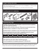
Optional High-Wind Bracket Pre-assembly 1 2 B x10 C A A If you have chosen to purchase the high-wind brackets (C), remove the screws in the existing brackets (B). Set brackets aside and save all screws for later. Slide the high-wind bracket (C) onto the bottom of the post (A), making sure that it is snug against the bottom. 3 C A Attach the high-wind bracket (C) using the screws that were removed in Step 1. The high-wind bracket uses an additional 14 screws that are included.
Support Post Installation " XX 'X 'X XX " 1 Using the chart on page 8, determine post layout. 2a Mark each post location. Each mark will be the exact center of the posts. 2b Standard bracket Optional high-wind bracket A A C B 1 1 2 2 For high wind areas, position post (A) and high-wind bracket (C) over mark and trace holes in bracket. Position post (A) and foot bracket (B) over mark and trace holes in bracket.
3a 3b Standard (3/16" drillbracket bit) (3/16" drill bit) V Drill holes using the 3/16" concrete drill bit (V) provided. Optional high-wind bracket (1/2" drill bit) (not included) For high-wind areas, use a 1/2" concrete drill bit (not included) to drill holes a minimum of 5" deep. 4 5 1 A 1 A 2 Position wood posts (A) so that they are parallel with each other. Using a string, align the tops of the posts.
6a 6b Optional bolts AA Z x4 x2 Use four concrete screws (Z) to secure. Tighten securely. DO NOT proceed with post covers until all wood posts are plumb and mounted securely. 6c As an option, additional 1/2" x 4" concrete screws/ bolts (AA)can be installed. Optional high-wind bracket 7 Repeat Steps 2-6 for remaining posts. AA x4 Use concrete screws/bolts (AA) to secure brackets. Tighten securely. DO NOT proceed with post covers until all wood posts are plumb and mounted securely.
Post Trim Installation 9 8 H D G F E Unpack post trim boxes and position trim close to each post in the order shown. Slide vinyl column (D) over wood post. Fit lower portion of vinyl column over wood spacers, until cover rests securely on concrete surface. 11 10 F E Slide the large base trim ring (E) over the top of the column until it rests on the concrete surface. Slide round trim ring (F) down column until it rests on the raised ledge.
13 12 G H Slide top trim ring (G) over column, making sure the rounded part is facing down and the square part is facing up. Slide top square post sleeve (H) over wood post. 14 Repeat Steps 10-13 for remaining posts. This is how the top post trim should look.
15 16 CC BB 1 DD 2 2 Hook temporary beam holder (BB) on top of the square post sleeve, facing direction of post, which will be supporting the opposite end of the beam. Repeat for opposite post. Insert wood block (CC), making sure the two holes in the wood block are facing upward. Insert a wood peg (DD) in each hole. Repeat for opposite post. This is how the temporary beam holder should look when it is positioned to hold the beam during beam installation.
Beam Assembly 17 1 2 J K Keep logo plate with screws. Unwrap beam sleeve (J) with the Suncast logo. Unscrew logo and remove. Set logo plate and gold screws aside to be reattached later. 18 19 1 K 6" 2 Slide 7' wood beam insert (K) out until 6" of the filler piece is exposed. Re-attach one side of the logo plate.
20 1 21 J 2 Measure the placement of the existing screw in the logo plate and transfer the measurement to the other end of the logo plate. Insert and tighten remaining screw. Slip opposite beam sleeve (J) over wood beam insert. Lift logo plate while sliding beam sleeve underneath. The seam should be snug where two sleeves meet. 22 3" X 23 3" L X 1/4" J J L x2 Unpack 1' wood beam inserts (L). Slide wood beam insert into hollow ends of beam sleeve (J).
24 X 25 6" Fasten a 1" screw (X) on the top edge of beam, 6" from the end of the beam. Note: Top edge of beam is determined by the logo plate orientation. 26 7 1/4" Measure and mark a line 7 1/4" in from the end of beam. Repeat on other end of beam. Note: Bottom edge of beam is determined by the logo plate orientation. 27 5" Repeat Steps 17-26 for remaining beams. U 1 1/2" Measure and mark holes 5" and 1 1/2" from bottom of beam.
29 28 J Position two 8' step ladders next to two posts. Double check the orientation of the temporary beam holders and make sure they are positioned to support the beams. Ensure the Suncast logo is facing outward and place the beam (J) onto the temporary beam holders. Center the beam on the two posts, making sure that an equal amount of beam protrudes past each post. 31 30 U W Using the pre-drilled holes that you drilled in Step 26, drill a 1/4" pilot hole into the post.
32 J The installed beam should look like this. Position next assembled beam (J) on opposite side of post. Make sure the pre-drilled holes are facing outward and towards the bottom. 33 34 1 Repeat steps 28-31 to install opposite beam. 1 DD BB 2 CC 3 Remove wood pegs (DD) and slide out wood blocks (CC) to remove temporary beam holders (BB). Reinstall them, as needed, on remaining posts.
35 36 I 1 I G H Y x4 2 Apply cement to the flange of post cover (I). Promptly slip post cover over the top of the top square post sleeve (H). Repeat for remaining posts. Note: It may be necessary to loosen the top of the beams to allow the cover to fit securely on post sleeve. Hold the top trim ring (G) against the beams and flush around the edges. Using four 2 1/2" pan head screws (Y), secure trim to beams. Repeat for other post.
39 40 FF X 1 X 1 X X X 2 X Refer to the chart to determine rafter clip spacing. Using a tape measure and pencil, mark the location of rafter clips. Attach a rafter clip (FF) directly over the top of the beam splice in the center of each beam with two 1" screws (X).
Rafter Assembly 42 43 N Repeat steps 37-41 to install remaining beams and rafter clips. P 42" Slide the 7' wood rafter insert (P) out of the rafter sleeve (N) until it protrudes 42". 44 45 1 1/2" N N X P O Insert a 1" screw (X) 1 1/2" from the end of the rafter sleeve (N). Slide rafter collar (O) onto 7' wood rafter insert (P) so that half of it rests on the rafter sleeve (N).
46 47 1 Repeat steps 43-46 to assemble remaining rafters. P 1 N 2 X Slide rafter sleeve (N) over 7' wood rafter insert (P) until the two vinyl sleeves are touching. Insert a 1" screw (X) next to the collar. Installing the Rafters 49 48 N Position two step ladders next to two posts. Place each end of a rafter (N) into the outer most rafter clips on the beams. At this point in the assembly process, all of the posts, beams, and rafter clips should be permanently installed.
50 51 X x4 Center the rafter on the beams, by measuring from each end of the rafter to the outside edge of the beam. Both of the measurements on each side of the beam should be equal. Using four 1" screws (X), secure rafter to the rafter clips. 52 53 N X x4 Using four 1" screws (X), secure rafter to the rafter clips on opposite end of beam. Place each end of a rafter (N) into the outer most clips on the beams.
55 54 Repeat steps 49-52 to center rafter and secure rafter to rafter clips. 4" Before moving on, measure the beams at the seam to make sure the spacing between the beams is 4". If needed, temporarily insert a 4" spacer while attaching remaining rafters. 56 Position the remaining rafters, fitting them inside the rafter clips. DO NOT attach any, until all have been centered and positioned. Adjust the rafters as needed, make sure all rafters line up perfectly straight before securing to rafter clips.
Assembling the Shades 57 58 R T 1 1 R T R 2 2 X X Slide the shade splice (T) halfway into shade (R). Insert a 1" screw (X) about 1" from end of the shade. Slide another shade (R) over shade splice (T), until it butts against exisiting shade. Insert a 1" screw (X) about 1" from end of the shade. Installing the Shades 59 60 R R 1 1/2" 1 1/2" Lay the two outside shades (R) on top of rafters.
X X 1/ 8" 12 1/ 8" 12 1/ 8" 61 12 " /8 21 1 Measure and mark rafters 12 1/8" from the center of the first shade for remaining shades. Prior to fastening the shades, sight the rafters and straighten shades as needed. 63 62 Secure remaining shades to rafters. Y After positioning the shades, begin at the corner and fasten shades using 2 1/2" pan head screws (Y). Ensure screws go through the top of the shade and into the rafter.
Installing Decorative Trim 64 M M Multi-purpose cement is provided to install decorative trim. Apply cement to inside ring of beam trim (M). Promptly tap beam trim into place, so that trim is snug and level. Repeat for remaining beams. 65 66 Q S S Q Apply cement to inside ring of shade trim (S). Promptly tap shade trim into place, so that trim is snug and level. Repeat for remaining shades. Apply cement to inside ring of rafter trim (Q).
67 X After beam, rafter, and shade trim have been installed, the pergola should look like this. x2 E Make sure that the large base trim ring (E) is square and parallel to the beam. Secure trim with two 1" screws (X) on opposite sides of the posts. Repeat for remaining posts. Congratulations! Your pergola is now ready to enjoy.
Warranty Suncast® Corporation, 701 North Kirk Road, Batavia, Illinois 60510 (Manufacturer) warrants to the original purchaser only that the enclosed product is free from material and workmanship defects under normal, household use at time of purchase. Defective product or part must be returned, freight prepaid, to the Manufacturer's address (Attention: Parts Department) along with proof of purchase.