
Installation Instructions


IMPORTANT SAFETY INSTRUCTIONS AND WARNINGS
General Warnings:
Please read and understand these instructions before you begin installation of your DRY04/DRY06.
Save these instructions for future reference.
To reduce the risk of fire, electric shock or injury to persons:
1. Never use this product to exhaust hazardous or flammable materials, vapors or gases.
2. Use this product only for its designed and intended purpose.
3. When the existing vent opening to the outside of the dwelling cannot be used and a new opening is required, use caution not to
cut through pipes or wires that may be in the wall.
4. Ducted fans must be vented outdoors.
5. Whenever venting air to the outside of a dwelling, adequate provision must be made for replacement air. Without replacement air,
negative pressure may develop. This will cause a deadly situation when fuel-burning equipment is used such as gas furnaces, gas
water heaters, etc. The negative pressure will cause exhaust gases from such equipment to enter the dwelling. These gases contain
deadly Carbon Monoxide. (As a general remark, install a Carbon Monoxide detector in your home). Follow the heating equipment
manufacturers’ guidelines and safety standards such as the National Fire Protection Association, the American Society of Heating,
Refrigeration and Air Conditioning Engineers and all applicable codes. If you are unsure about this matter, you must consult a
certified heating and ventilating contractor.
6. Before cleaning or performing service on your DRY04/DRY06, make sure that the electricity is shut-off and make provisions to
prevent accidental turning-on of power such as locking the service panel or attaching a very prominent warning sign on the service
panel.
7. The fan impeller of your DRY04/DRY06 is powerful enough to cause serious injury if contacted. Appropriate safety precautions
must be taken during installation, servicing and operation.
8. Qualified individuals must do the installation and wiring in accordance with all applicable codes & standards including fire rated
construction.
Installation Guidelines:
Refer to Fig. 1 for suggested installations.
1. The mechanical and electrical installation of your DRY04/DRY06 must conform to all applicable national and local codes and
standards. If unfamiliar with these codes and standards, you must consult with certified and qualified commercial installers.
2. Never expose your DRY04/DRY06 to air temperatures in excess of 140°F. (60°C).
3. Do not use the DRY04/DRY06 if the instructions of your clothes dryer specifically warn against the use of a clothes dryer booster
fan. Find those instructions and review them carefully. If you cannot locate these instructions, contact the manufacturer for a new
set of instructions before proceeding with the installation of your DRY04/DRY06.
4. There are important rules concerning the length of duct from your dryer to the outside of the dwelling. It is unlikely that you will
need a booster fan if the total length of the duct is less than 15 feet. This is assuming that the duct is at least 4” in diameter, has a
smooth and clean internal surface, is galvanized sheet metal and that the outside vent is unobstructed.
5. Do not install your DRY04/DRY06 closer than 6 feet (1.8 meters) to the dryer air outlet.
6. Do not install your DRY04/DRY06 in a duct with a total equivalent length of less than 25 feet (7.5 meters).
7. Do not install your DRY04/DRY06 in a duct with a total equivalent length greater than 140 feet (46 meters).
8. A lint trap (field supplied) must be installed between the dryer and your DRY04/DRY06 in the event the DRY04/DRY06 is located
less than 15 feet (4.5 meters) (linear feet, not equivalent) from the air exhaust of the dryer.
9. Use only galvanized 4” diameter sheet metal duct pipe and bends. Flexible metal duct may be used if allowed by the applicable
standards and codes.
10. It is best to install your DRY04/DRY06 as close to the duct outside outlet as possible.
11. Your DRY04/DRY06 must be installed where it is comfortably accessible for required maintenance and service.
12. Ensure that all components of your installation are securely fastened to rigid surfaces.
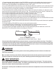
13. You may install two small lengths of flexible duct with hose clamps (field supplied) where the metal ducts connect to the
DRY04/DRY06. This will help reduce vibration and resulting noise. See Fig 2.
To calculate “equivalent” feet, measure the total
length of the metal straight duct sections and
add 5 feet (1.5 meters) for each bend that is
installed. Then add another 5 feet (1.5 meters)
for the screened outside exhaust hood.
Fig. 2
METAL DUCT METAL DUCT
OPTIONAL FLEXIBLE DUCT COUPLINGS TO REDUCE
VIBRATION NOISE. (FIELD SUPPLIED) USE CLAMPS TO SECURE.
Ensure that the airflow through the duct and booster fan does not exceed the free airflow of your dryer. Free airflow is
the airflow from the fan inside your dryer without any duct attached and can be found in the instructions provided by its
manufacturer. Over-boosting may result in longer drying times because heat is removed so fast that the heating element
in your dryer cannot maintain the desired drying air temperature.
The installation work and electrical wiring must be carried out by qualified persons and conform to all national and
local codes and standards.
Make sure that the electricity is shut-off before starting the electrical work and make provisions to prevent accidental
turning-on of power such as locking the service panel or attaching a prominent warning sign on the service panel.
240 VAC Dryer Connections:
1. After installing your DRY04/DRY06 in the chosen location you will need to bring electric power to the fan.
2. Locate the power feed wires to the outlet that your dryer is plugged into or electrical box the dryer is hardwired into.
3. Install a 4”x 4” deep electrical box next to the box of the dryer connection (outlet or hardwired) and connect the two boxes using
rigid ½” conduit and connectors. Then install the Current Switch provided into this box.
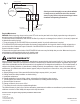
Refer to the appropriate diagram for dryers that have a plug-in (Figure 3) or are hardwired into an electrical box. (Figure 4)
Electrical Installation:
Refer to Figures 3 and 4, for required wiring. Refer to the Current Switch Installation Guide for further details.
Since the dryer operates on 240 VAC, there will be 2 breakers for the dryer in the service panel. This can be one large
breaker with 2 handles or 2 separate breakers. The handles on these breakers may or may not be connected with a rod
between the switches. Make sure both breakers are turned OFF!
Do not turn the electrical power back ON until all electrical connections are completed and secure and all electrical boxes
are covered.
4. The majority of electric dryers run on 240 VAC. You will find 4 wires in the dryer outlet box. Two individual 120 VAC conductors
(usually Black or Red) are each supplying 120 VAC from separate breakers in the service panel. The other wires are a White
common (neutral) conductor and the Green (grounding) conductor.
If you find different color wires or more or fewer wires in this box, you MUST consult a qualified electrician.
5. Disconnect the White common (neutral) conductor from the dryer outlet (Figure 3) or disconnect the White wire in hardwired
installations (Figure 4) and extend this conductor with a length of wire that is identical to the gauge and temperature rating of the
White conductor.
6. This extended White wire will be run into the Current Switch 4” x 4” box and through the hole in the Current Switch and then
return to the terminal on the dryer outlet (Figure 3) or the White wire going to the clothes dryer. (Figure 4). The electricity going
through this White conductor looped through the Current Switch makes the Current Switch turn ON when the dryer is operating.
7. Check the wiring and connections and re-install the electrical dryer outlet and cover plate.
AC CURRENT SWITCH MODEL: SW100
WIRING DIAGRAM WHEN THE DRYER IS PLUGGED INTO OUTLET
BOTH BLACK WIRES, EXTENDED WHITE WIRE AND
GREEN WIRE ARE CONNECTED TO DRYER OUTLET
B
L
A
C
K
B
L
A
C
K
G
R
E
E
N
SWITCH RATING
AC CURRENT SWITCH
T1
C
US
L1
SWITCH RATING
120VAC(MAX)
1.2 - 40
2.5AMP(MAX)
AMP - TURNS
120 VAC FROM
FUSE PANEL
120 VAC CURRENT
SWITCH OUTLET BOX
EXTENDED
WHITE
WHITE
GREEN
POWER FROM
FUSE PANEL
120 VAC TO REMOTE DEVICE
ie CENTRAX CENTRIFUGAL FAN
W
H
I
T
E
EXTENDED
WHITE
Fig. 3
AC CURRENT SWITCH MODEL SW100
WIRING DIAGRAM WHEN DRYER IS HARDWIRED
Fig. 4
120 VAC Fan Connections:
8. Run 3 new wires (minimum 14 Gauge, 105ºC), Black (line or hot), White (common or neutral) and Green (ground) 120 VAC to
the service panel with a new breaker, or pick up the Black, White and Green wires from a nearby 120 VAC outlet. The new Black
conductor connects to terminal L1 on the Current Switch.
9. Run a new Black conductor from the DRY04/DRY06 to terminal T1 on the Current Switch. The new White and Green wires
connect directly to the terminal block of the DRY04/DRY06.
10. All new wiring must be rated 14 Gauge minimum, 105ºC. and installed in rigid ½” conduit or metal flexible conduit terminated
at electrical boxes with the correct conduit connectors.
11. Install the cover plate on the box containing the Current Switch.
Required Maintenance:
WARNING: Before beginning, always turn the power OFF at the service panel and lock or display a prominent tag on the panel to
ensure the power is not accidentally turned back on.
To reduce the need for maintenance, make sure the lint filter of your dryer is not damaged, has no holes in it, is securely in place and
is cleaned after each drying load.
1. The motor bearings of your DRY04/DRY06 are permanently sealed. No periodic maintenance is required.
2. The DRY04/DRY06 fan housing and impeller may become contaminated with lint. Inspect the interior of the fan at least twice a
year and more often if reduced air output or vibration of the DRY04/DRY06 is observed. Do not operate your DRY04/DRY06 if
excessive vibration is noticed.
3. Remove the duct pipe from the intake of the DRY04/DRY06 and remove any lint buildup that you notice. Make sure that you do
not dislodge the metal fan balancing clips on the impeller vanes.
4. Reconnect the duct intake pipe and turn the power back ON.
Check your work thoroughly to ensure the installation
is totally correct to reduce the risk of fire, electrical
shock or injury. Refer to all previous warnings in these
installation and operating instructions.
MOTOR
120VAC, 60Hz, TP
120VAC, 60Hz
N L
GREEN (GROUND)
NEW WHITE
(COMMON/NEUTRAL)
BLACK
(LINE) FROM L1 ON
CURRENT SWITCH
NEW GREEN
(GROUND)
BROWN
BLACK (LINE)
WHITE (NEUTRAL)
WIRE NUT
CAPACITOR
Fig. 5
Subject to the following limitation, Suncourt Inc. (manufacturer) warrants that this dryer booster kit will, for 5 (five) years from date of
original purchase, remain free from appearance of defects in workmanship or materials when installed in accordance with all appli-
cable codes and standards and fire rated construction in the application for its designed and specified use. This Limited Warranty is
subject to the following limitations: (a) manufacturer’s liability is limited to the replacement or repair of the unit, as decided by the
manufacturer; (b) a defective unit must be returned, prepaid, with proof of purchase, to Suncourt Inc, and (c) this Limited Warranty
does not apply if:
a. Shipping damage occurs. Claims must be filed with the freight company within 1 (one) week.
b. Damage results from faulty installation or electrical wiring.
c. Inadequate maintenance.
d Damage results from: Incorrect wiring, voltage, voltage spikes from lightning or other sources.
f. The DRY04/DRY06 is altered or modified in any form whatsoever, including unauthorized repair.
g. Suncourt ID label is removed.
h. Damage or failure is due to an act of God.
i. This product is used in other than a residential application.
This Limited Warranty is given in lieu of all other warranties, guarantees and conditions on manufacturer’s part and manufacturer
shall have no tortious or other liability with respect to this dryer booster kit.
Suncourt reserves the right to change product specifications without notice.
Fig. 1
INSTRUCTIONS FOR THE
CLOTHES DRYER VENT BOOSTER
MODEL: DRY04/DRY06
THE SUNCOURT DRYER VENT KIT IS ONLY APPROVED
FOR INSTALLATIONFOR ELECTRIC CLOTHES DRYERS.
CRITICAL WARNING:
WARNING:
VERY IMPORTANT:
B
L
A
C
K
B
L
A
C
K
G
R
E
E
N
SWITCH RATING
AC CURRENT SWITCH
T1
C
US
L1
SWITCH RATING
120VAC(MAX)
1.2 - 40
2.5AMP(MAX)
AMP - TURNS
120 VAC FROM
FUSE PANEL
120 VAC CURRENT
SWITCH OUTLET BOX
EXTENDED
WHITE
EXTENDED
WHITE
WHITE
BLACK
GREEN
BLACK
POWER FROM
FUSE PANEL
POWER TO DEVICE
ie CLOTHES DRYER
120 VAC TO REMOTE DEVICE
ie CENTRAX CENTRIFUGAL FAN
BLACK
BLACK
W
H
I
T
E
LIMITED WARRANTY
SUNCOURT INC.
P.O. Box 40
Durant, IA 52747-0040
1.800.999.FANS (3267)
www.suncourt.com
WNTDRY-0914-A01
PRINTED IN USA