
Installation Guide

The final steps:
Screw the thermostat to the wall.
Connect the Transformer 110/120 Volt wires inside the junction box. See IMPORTANT WARNINGS above !
Connect the GREEN wire from the Transformer to the GREEN or bare copper wire inside the junction box.
Connect either of the BLACK wires of the Transformer to the WHITE wire inside the junction box.
Connect the remaining BLACK wire of the Transformer to the BLACK wire inside the junction box.
Place the cover (with the Transformer mounted to it) on the junction box, making sure that no wires are pinched between the
cover and the junction box.
Now review your installation. If you are positive that everything has been installed safely and securely, you may turn on the
breaker on your house power panel.
MAINTENANCE
Suncourt® recommends that you clean your damper at regular intervals to keep it free from lint, dust and debris. The damper
must never be exposed to temperatures over 140˚F (60˚C).
OPERATING INSTRUCTIONS
1. Set the switch on the thermostat marked ‘ON-AUTO’ , ‘ON-OFF-AUTO’, ‘ON-OFF’ or similar wording, to the ‘ON’ position.
2. Heating Season: Set the thermostat to ‘HEAT’. Then adjust the thermostat to the chosen temperature (e.g. 55˚F).
As long as the temperature in the room is 55˚F or higher, the damper will be closed. If the temperature in the room
falls below 55˚F, the damper will open.
3. Cooling Season: Set the thermostat to ‘COOL’. Then adjust the thermostat to the chosen temperature (e.g. 85˚F).
As long as the temperature in the room is 85˚F or lower, the damper will remain closed. If the temperature in the
room goes higher than 85˚F, the damper will open.
THREE (3) YEAR WARRANTY
Subject to the following limitations, Suncourt® Inc. (manufacturer) warrants that the ZoneMaster™ will, for 3 (three) years from
date of original retail purchase, remain free from appearance of defects in workmanship or materials. This warranty is subject to
the following limitations: (a) manufacturer’s liability is limited to the replacement or repair of the unit, as decided by the
manufacturer; (b) a defective unit must be returned, prepaid , with proof of purchase, to the point of purchase or as instructed
below; and (c) this warranty does not apply to defects resulting from the alteration, abuse, accidental damage, unauthorized
repair or misuse of the unit. This warranty is given in lieu of all other warranties, guarantees and conditions on manufacturer’s
part, and the manufacturer shall have no tortious or other liability in respect to this ZoneMaster™.
Suncourt® Inc. • 500 W. Second Avenue • P.O. Box 40 • Durant, IA 52747-0040 • 1.800.999.FANS (3267) • www.suncourt.com
WNT165-1004
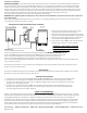
Low voltage wiring:
Refer to the wiring diagram below for electrical connections. It is recommended that you leave at least 1’ (30 cm) of slack wire at
each component wired to ease future servicing.
WIRING INSTRUCTIONS FOR ZONE MASTER™ DAMPERS
Transformer installation:
IMPORTANT WARNING: Locate the breaker on your house power panel that controls the 110/120 Volt AC supply to the wires in
the junction box that you selected to mount the Transformer on. Use a voltage detector, voltmeter or other suitable instrument
to make sure that all power to that junction box is OFF. Identify an existing wiring junction box near the location desired. Verify
that the correct wires are available in this box. There needs to be: Black wire (line or hot), White wire (neutral) and a Green or bare
copper wire (ground). The cover plate of that junction box must have a “knockout”. This “knockout” must be removed to make the
hole for the stud of the Transformer to mount through. Thread the Transformer leads through the hole and
securely mount the Transformer to the cover plate. Tighten the nut snug only.
WARNING: Over-tightening will break the plastic stud of the Transformer. DO NOT connect the Transformer wires at this time.
1. Run one wire from either Transformer low voltage
terminal to either terminal on the Damper.
2. Run one wire from the other Transformer low voltage
terminal to the terminal marked “R” on the thermostat.
3. Run one wire from the other terminal on the Damper
to the terminal marked “W” on the thermostat.
4. Connect the terminals “W” and “Y” on the thermostat
together with a short piece of wire (jumper).
THE WIRING IS NOT POLARITY SENSITIVE
CONNECT EITHER SCREW ON TERMINAL
BLOCK OR TRANSFORMER.
HEAT COOL THERMOSTAT
OR OTHER SWITCHING DEVICE
STUD MOUNT
TRANSFORMER
DAMPER UNIT
WY
GR
GREEN
BLACK
BLACK
TERMINAL
JUMPER