
Warranty


SX232B: Parts Breakdown & Operating Manual 4 Rev. 6/27/16
OPERATION
Always turn off the air supply, drain hose of air pressure and
detach tool from air supply before installing, removing or adjusting
any part or accessory on this tool, or before performing any
maintenance on this tool.
Bonded abrasive mounted point grinding wheels, rotary files and
carbide burrs can be mounted providing their speed rating exceeds
the speed of the Die Grinder. The shank size of the mounted accessory
must match the collet size fitted in the Die Grinder. Insert the shank
of the mounted point as far as possible into the collet and tighten the
nut using the supplied wrenches. Minimum shank gripping length
must be 10mm.
After mounting a new point, start the Die Grinder under bench and
run for a few seconds. If the Die Grinder starts to vibrate when first
fitting a mounted point or during operation, immediately remove from
service. If Die Grinder is dropped, replace bonded abrasive mounted
point grinding wheel, rotary file or carbide burr.
When using the Die Grinder, be careful not to exert excessive force
which could be hazardous and cause mounted spindle to bend or
break.
NOTE: During operation, safety goggles should always be worn to
guard against flying debris (users and bystanders).
WARNING: Never mount a grinding wheel, cut-off wheel, router
cutter or drill bit on a Die Grinder. Never use an arbor, mandrel
or any other adapter to convert the Die Grinder for any other
application.
AIR SUPPLY
Tools operate on a wide range of air pressures. It is recommended
that air pressure measures 90 psig at the tool with the trigger fully
depressed and no load applied to the tool. Higher pressure (over 90
psig; 6.2 bar) raises performance beyond the rated capacity of the
tool, which will shorten tool life and could cause injury.
Always use clean, dry air. Dust, corrosive fumes and/or water in the
air line will cause damage to the tool. Drain the water from air lines
and compressor prior to running tool. Clean the air inlet filter screen
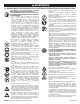
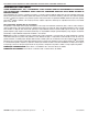
weekly. The recommended hookup procedure can be viewed in FIG. 1.
The air inlet used for connecting air supply has standard 1/4" NPT.
Line pressure should be increased to compensate for unusually long
air hoses (over 25 feet). Minimum hose diameter should be 3/8" I.D.
and fittings should have the same inside dimensions and be tightly
secured.
Ensure an accessible emergency shut off valve has been installed
in the air supply line and make others aware of its location.
TROUBLESHOOTING
Other factors outside the tool may cause loss of power or erratic
action. Reduced compressor output, excessive drain on the air line,
moisture or restrictions in air pipes or the use of hose connections
of improper size or poor conditions may reduce air supply. Grit or
gum deposits in the tool may cut power and may be corrected by
cleaning the air strainer and flushing out the tool with gum solvent
oil or an equal mixture of SAE #10 and kerosene. If outside conditions
are in order, disconnect tool from hose and take tool to your nearest
authorized service center.
LUBRICATION AND MAINTENANCE
Lubricate the air motor daily with high quality air tool oil. If no air line
oiler is used, run 1/2 oz. of oil through the tool. The oil can be squirted
into the tool air inlet or into the hose at the nearest connection to
the air supply, then run the tool. A rust inhibitive oil is acceptable for
air tools.
WARNING: After an air tool has been lubricated, oil will discharge
through the exhaust port during the first few seconds of operation.
The exhaust port must be covered with a towel before applying air
pressure to prevent serious injury.
Operating Instructions • Warning Information • Parts Break down
Drain Daily
Regulator Oiler Quick Coupler Leader
Hose
Nipple
Do Not Install
Quick Coupling
Here
Nipple
Filter
Air Supply
Whip Hose
fig. 1.