
Home Theater Server User Manual

10
User’s Manual
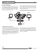
CHAPTER 2 – Connections and Remote
TGM-100
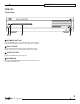
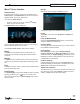
Rear View
1 2 3 4 5 6
14 13 1112 9
8
710
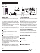
1
HDMI VIDEO
Use the HDMI connector to connect your TGM-100 to a digital
at-panel television or projector. HDMI Output is usually connect-
ed to the main television used for viewing movies in your home.
This connector has the ability to send up to 1080p video as well
as 5.1 Channel Dolby, DTS and stereo over one cable. To take
advantage of the Surround Sound Audio Formats, it is necessary
to connect the audio output to a device capable of decoding the
surround sound signal.
• If your digital TV can decode the signal, simply connect it to the
HDMI socket on the back of the TGM-100.
• If your digital TV does not decode the signal, noise may be emit-
ted by the TV’s speakers. In this case you should mute the TV’s
volume and connect an amplier with this capability to the digital
output (
9
or
10
) of the TGM-100.
2
DVI VIDEO
Connect to TGM-DVC DVI to Composite Video Converter to
control the TGM-100 using the dedicated Touch panel UI.
3
ESATA
Use this port to connect a Sunre eSATA drive.
4
COMPONENT VIDEO OUT
Connect the Y, P
B
and P
R
Component Video Out of the TGM-100
to the Y, P
B
and P
R
COMPONENT VIDEO IN of a suitable TV to
display the TV User Interface (up to 1080i). You may also need to
switch the TV to the relevant input to display the picture.
5
COMPOSITE VIDEO OUT
Connect the composite Video Out of the TGM-100 to the com-
posite input of a suitable PAL or NTSC TV to display the TV User
Interface. You may also need to switch the TV to the relevant
input to display the picture.
6
S-VIDEO OUT
Connect the S-VIDEO output of the TGM-100 to the S-VIDEO
input of a suitable PAL or NTSC TV to display the TV User Inter-
face. You may also need to switch the TV to the relevant input to
display the picture.
7
ANALOG AUDIO OUT
This analog audio output may be connected to the input jacks of a
pre-amplier, receiver or whole-house controller.
8
IR INPUT
The IR INPUT connection allows remote control information to be
carried from third-party controllers directly into the TGM-100.
9
COAXIAL DIGITAL AUDIO OUT
By connecting the coaxial jack to a digital audio component (D/A
converter, A/V amplier etc.), digital signals from the TGM-100
can be transmitted directly from the system without rst being con-
verted to analog. This output may not be used for making a digital
copy of your media.
10
OPTICAL DIGITAL AUDIO OUT
The digital optical output can be used to transmit high quality
audio to a device with a digital optical input (D/A converter, A/V
amplier etc.) using an optical ber cable. The advantage of using
the optical output is that it has low signal loss and is completely
isolated from the ground loop.This output may not be used for
making a digital copy of your media.
11
LAN (ETHERNET) PORT
The Ethernet port is used to connect the TGM-100 to a Gigabit
network or high speed Internet connection.
12
USB PORT
Allows the TGM-100 to communicate with supported USB
devices.
13
RS-232 PORT
Allows the TGM-100 to be controlled from third-party control
systems.
14
POWER CONNECTOR
Connect the supplied power cord to this connector to provide
power to the unit.