Preface About SunFounder SunFounder is a technology company focused on Raspberry Pi and Arduino open source community development. Committed to the promotion of open source culture, we strive to bring the fun of electronics making to people all around the world and enable everyone to be a maker. Our products include learning kits, development boards, robots, sensor modules and development tools. In addition to high quality products, SunFounder also offers video tutorials to help you make your own project.
Contents Components List........................................................................................................................................................ 1 Get Started................................................................................................................................................................10 Arduino.......................................................................................................................................................
Lesson 20 Blinking an LED by Potentiometer................................................................................................... 70 Lesson 21 Tilt Switch................................................................................................................................................ 72 Lesson 22 Buzzer.......................................................................................................................................................
Components List No. Name Qty.
Barometer-BMP280 1 6 RTC-DS1302 1 7 Flame Sensor 1 8 Gas Sensor 1 9 Humiture Sensor 1 2
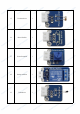
10 Joystick PS2 1 11 Button 1 12 Mercury Switch 1 13 Touch Switch 1 14 Photo-interrupter 1 3
15 Photoresistor 1 16 Reed Switch 1 17 Potentiometer 1 18 Relay Module 1 19 Thermistor 1 4
20 Tilt-Switch 1 21 Active Buzzer 1 22 Passive Buzzer 1 23 24 Temperature Sensor DS18B20 RGB LED 1 1 5
25 IR Receiver 1 26 Dual-Color LED 1 27 Sound Sensor 1 28 Rotary Encoder 1 29 Laser Emitter 1 6
30 Tracking Sensor 1 31 IR Obstacle Sensor 1 32 Color Sensor 1 33 34 AD/DA Converter PCF8591 Raindrop Sensor 1 1 7
35 Ultrasonic 1 36 Remote Controller 1 37 I2C LCD1602 1 38 Breadboard 1 39 USB Cable 1 40 5-Pin Anti-reverse Cable 5 8
41 42 43 44 45 46 47 3-Pin Anti-reverse Cable 4-Pin Anti-reverse Cable 2-Pin Anti-reverse Cable 2-Pin Ribbon Cable (F to F) Dupont Wire (M to F) Dupont Wire (M to M) Dupont Wire (F to F) 5 5 2 1 10 10 10 9
Get Started Note: Before starting your own project, you must download the file Sensor Kit V2.0 for Arduino.zip on our official website by visiting LEARN -> Get Tutorials -> Sensor Kit V2.0 for Arduino and unzip it. Arduino Description Arduino is an open source platform with simple software and hardware. You can pick it up in short time even if you are a beginner. It provides an integrated development environment (IDE) for code compiling, compatible with multiple control boards.
Nano Board, SunFounder Mars Board and SunFounder Mercury Board. The Uno Board and the Mars Board share the same kind of pins at the same position. And the pins of the first half part on the Mega 2560 are the same as those on the Uno. The difference lies in that on the Mega 2560 board, the I2C pin (SDA) and pin SCL don't correspond to pin A4 and A5 but to pin 20 and 21. On the other hand, the Nano and the Uno also share the same kind of pins at the same position.
Find the one that suits your operation system and click to download. There are two versions of Arduino for Windows: Installer or ZIP file. You're recommended to download the former. Just download the package, and run the executable file to start installation. It will download the driver needed to run Arduino IDE. After downloading, follow the prompts to install.
concise. If you don't want to use the library, you can also write that function definition directly. Though as a result, the code will be long and inconvenient to read. Add libraries Some libraries are already built in the Arduino IDE, when some others may need to be added. So now let's see how to add one. There are two methods for that. Method 1 Directly import the library in Arduino IDE (take LiquidCrystal_I2C as an example below).
Method 2 Directly copy the library to libraries/Arduino path. This method can copy all libraries and add them at a time, but the drawback is that it is difficult to find libraries/Arduino. Step 1: Click File -> Preferences and on the pop-up window you can see the path of the libraries folder in the textbox as shown below. Step 3: Copy all Libraries in the path Sensor Kit V2.0 for Arduino\Library\. Step 4: Go to the path above and you will see there is a Libraries folder, click to open it.
For more details about Arduino IDE, go to Learning->Getting started->Foundation on the arduino.cc and click Arduino Software (IDE) on the page: http://www.arduino.cc/en/Guide/Environment. If your sketch fails the upload, on the same page click Troubleshooting http://www.arduino.cc/en/Guide/Troubleshooting. Notes: - If your computer is running on the Windows XP system, the new version IDE will prompt errors when running the code. You are recommended to download the Arduino 1.0.5 or Arduino 1.0.6.
Introduction Lesson 1 Display by I2C LCD1602 As we all know, though LCD and some other displays greatly enrich the man-machine interaction, they share a common weakness. When they are connected to a controller, multiple IOs will be occupied of the controller which has no so many outer ports. Also it restricts other functions of the controller. Therefore, LCD1602 with an I2C bus is developed to solve the problem. I2C bus is a type of serial bus invented by PHLIPS.
Step 2: Open the code file In the folder Sensor Kit V2.0 for Arduino you just downloaded and unzipped, you can see the folder for the corresponding lesson which includes two folders: code (the sketch) and circuit (Fritzing file). Go to the code folder and find the .ino file (.ino is the format of the sketch). Then double click to open it. You can also open an empty .ino file and type in the code we provide. Step 3: Select the Board and Port Before uploading the code, you need to select the Board and Port.
Then select Tools ->Port. Your port should be different from mine. Step 4: Upload the sketch to the SunFounder Uno board Click the Upload icon to upload the code to the control board. If "Done uploading" appears at the bottom of the window, it means the sketch has been successfully uploaded.
You should now see your I2C LCD1602 display the flowing characters: "SunFounder" and "hello, world".
Lesson 2 Analog Hall Sensor Introduction Based on the Hall Effect, a Hall sensor is a one that varies its output voltage in response to a magnetic field. Hall sensors are used for proximity switching, positioning, speed detection, and current sensing applications. Hall sensors can be categorized into linear (analog) Hall sensors and switch Hall sensors.
Electricity carried through a conductor will produce a magnetic field that varies with current, and a Hall sensor can be used to measure the current without interrupting the circuit. Typically, the sensor is integrated with a wound core or permanent magnet that surrounds the conductor to be measured. In this experiment, when the sensor approaches the magnet, the value of pin A0 will change.
Step 2: Open the code file Step 3: Select correct Board and Port Step 4: Upload the sketch to the SunFounder Uno board Now, put a magnet close to the Hall sensor. The voltage of D0 changes from high to low, and then the LED on the sensor and that attached to pin 13 of the SunFounder Uno light up. You can see the value of A0 and D0 on Serial Monitor.
Lesson 3 Switch Hall Sensor Introduction A switch Hall sensor consists of voltage regulator, Hall element, differential amplifier, Schmitt trigger, and output terminal. It outputs digital values. Components - 1 * SunFounder Uno board - 1 * USB data cable - 1 * Switch Hall sensor module - 2 * 3-Pin anti-reverse cable - 1 * Passive buzzer - 1 * Magnet Experimental Principles Hook up the switch Hall sensor module with pin 8 of the SunFounder Uno, and the buzzer to pin 7.
Experimental Procedures Step 1: Build the circuit The wiring between the switch Hall sensor and SunFounder Uno board: Switch Hall Sensor SunFounder Uno SIG 8 VCC 5V GND GND The wiring between the passive buzzer and SunFounder Uno board: Passive Buzzer SunFounder Uno SIG 7 VCC 5V GND GND Step 2: Open the code file Step 3: Select correct Board and Port Step 4: Upload the sketch to the SunFounder Uno board 24
Now, if a magnet approaches the switch Hall sensor, the indicator light on the sensor will light up and the buzzer will beep. At the same time, the LED attached to pin 13 on the SunFounder Uno board will also light up.
Lesson 4 Analog Temperature Sensor Introduction A temperature sensor is a component that senses temperature and converts it into output signals. By material and component features, temperature sensors can be divided into two types: thermal resistor and thermocouple. Thermistor is one kind of the former type. It is made of semiconductor materials; most thermistors are negative temperature coefficient (NTC) ones, the resistance of which decreases with rising temperature.
Experimental Procedures Step 1: Build the circuit 27
Step 2: Open the code file Step 3: Select correct Board and Port Step 4: Upload the sketch to the SunFounder Uno board Now, touch the thermistor, and the LED on the analog temperature sensor module and that attached to pin 13 of the SunFounder Uno will go out.
Lesson 5 Temperature Detection by Thermistor Introduction As mentioned in Lesson 4, thermistors are the most sensitive temperature sensors because their resistance changes acutely with temperature changes. Therefore, the thermistor sensor module measures temperature sensitively though it can output only analog signals. The module is often used to detect the temperature changes in ambient environment.
Experimental Procedures Step 1: Build the circuit Step 2: Open the code file Step 3: Select correct Board and Port Step 4: Upload the sketch to the SunFounder Uno board Now, you can see the current value of temperature displayed on the LCD, in both Celsius and Fahrenheit degrees.
Lesson 6 Auto-flash LED Introduction The 7-color auto-flash LED module can automatically flash built-in colors after power on. It can be used to make quite fascinating light effects. Components - 1 * SunFounder Uno board - 1 * USB data cable - 1 * 7-color auto-flash LED module - 1 * 3-Pin anti-reverse cable Experimental Principle When it is power on, the 7-color auto flash LED will flash built-in colors.
Now, you should see the LED flashing seven colors.
Introduction Lesson 7 Barometer BMP280 The BMP280 Digital Barometer is developed by Bosch Sensortec. Compared with the previous BMP085, BMP180, and BMP183, this BMP280 barometer comes with a higher performance and the smallest size in the industry. The BMP280 is an absolute barometric pressure sensor especially designed for mobile applications. The sensor module is housed in an extremely compact 8-pin metal-lid LGA package with a footprint of only 2.0x2.5mm2 and 0.95mm package height.
- Power VCC: power pin. The working voltage for the chip is 1.71-3.6V. Since the module integrates a 3.3V voltage regulator, the power supply can be either 3.3V or 5V. If you are using an Arduino board, you're recommended to use a 5V power supply. 3.3V: the output of the voltage regulator, meaning you can provide the chip with a 3.3V for power here. GND: common ground for power and logic BMP280 supports I2C and SPI communication and the module keeps both ports.
SPI Wiring BMP280 Uno/Mega2560 VCC 5V GND GND SCK 13 /Pin 52 SDO 12/Pin 50 SDI 11/ Pin 51 CS 10 /Pin 53 35
Step 2: Open the code file If you adopt the I2C way for connecting, double-click BMP280_I2C.ino under Sensor Kit V2.0 for Arduino\Lesson 7 Barometer\BMP280\Code \BMP280_I2C to open it; for the SPI way, double-click BMP280_SPI.ino under Sensor Kit V2.0 for Arduino\Lesson 7 Barometer\BMP280\ Code\BMP280_SPI.
Lesson 8 Real-time Clock Module Introduction Nowadays there are many popular serial clock circuits such as DS1302, DS1307, PCF8485, etc. They are widely used for simple interface, low cost, and ease of use. In this lesson, we will use the DS1302 real-time clock (RTC) module to obtain current date and time.
The schematic diagram of the module: Experimental Procedures Step 1: Build the circuit The wiring between DS1302 and SunFounder Uno board is as shown below: DS1302 SunFounder Uno SCL 7 SDA 6 RST 5 VCC 3.
Step 2: Open the code file Step 3: Select correct Board and Port Step 4: Upload the sketch to the SunFounder Uno board Now, you can see the current date and time information displayed on the I2C LCD1602.
Lesson 9 Flame Alarm Introduction A flame sensor module performs detection by capturing infrared wavelengths from flame. It can be used to detect and warn of flames. Components - 1 * SunFounder Uno board - 1 * USB data cable - 1 * Flame sensor module - 1 * Passive buzzer module - 1 * 4-Pin anti-reverse cable - 1 * 3-Pin anti-reverse cable Experimental Principle There are several types of flame sensors. In this experiment, we will use a far-infrared flame sensor.
Experimental Procedures Step 1: Build the circuit The wiring between the flame sensor and SunFounder Uno board: Flame Sensor SunFounder Uno D0 8 A0 A0 VCC 5V GND GND The wiring between the passive buzzer and SunFounder Uno board: Passive Buzzer SunFounder Uno SIG 7 VCC 5V GND GND Step 2: Open the code file Step 3: Select correct Board and Port Step 4: Upload the sketch to the SunFounder Uno board 41
Now, ignite a lighter near the flame sensor. Then the buzzer will beep, and the LED on the flame sensor module and that attached to pin 13 of the SunFounder board will light up.
Lesson 10 Flammable Gas Detection Introduction Gas Sensor MQ-2 is a sensor for flammable gas and smoke by detecting the concentration of combustible gas in the air. They are often used in gas detecting equipment for smoke and flammable gasses such as LPG, i-butane, propane, methane and alcohol in household, industry or automobile.
Experimental Procedures Step 1: Build the circuit Step 2: Open the code file Step 3: Select correct Board and Port Step 4: Upload the sketch to the SunFounder Uno board Now, ignite a lighter. Then the sensor detects the gas emitted. Thus, the LED on the gas sensor and that attached to pin 13 on the SunFounder Uno board will light up. Also you can see the value at A0 and D0 printed on Serial Monitor. Note: It is normal that the gas sensor generates heat.
Lesson 11 Humiture Detection Introduction The digital temperature and humidity sensor DHT11 is a composite sensor that contains a calibrated digital signal output of temperature and humidity. The technology of a dedicated digital modules collection and the temperature and humidity sensing technology are applied to ensure that the product has high reliability and excellent long-term stability.
The schematic diagram Experimental Procedures Step 1: Build the circuit Step 2: Open the code file Step 3: Select correct Board and Port Step 4: Upload the sketch to the SunFounder Uno board 46
Now, you can see the value of current humidity and temperature displayed on the LCD.
Lesson 12 Joystick PS2 Introduction A joystick is an input device consisting of a stick that pivots on a base and reports its angle or direction to the device it is controlling. Joysticks are often used to control video games and robots. A Joystick PS2 is used here.
Experimental Procedures Step 1: Build the circuit The wiring between the Joystick PS2 and SunFounder Uno board: Joystick PS2 SunFounder Uno GND GND VCC 5V Bt 7 x A0 y A1 Step 2: Open the code file Step 3: Select correct Board and Port Step 4: Upload the sketch to the SunFounder Uno board 49
Now, push the rocker and the coordinates of X and Y axes displayed on Serial Monitor will change accordingly; press the button, and the coordinate of Z=0 will also be displayed.
Lesson 13 Controlling an LED by Button Introduction As you can see, an LED has been attached to pin 13 on most of the SunFounder boards already. So just a button module can be used to build a simple circuit to make the LED light up. Components - 1 * SunFounder Uno board - 1 * USB data cable - 1 * Button module - 1 * 3-Pin anti-reverse cable Experimental Principle Since the LED has been attached to pin 13, just connect the button module to digital pin 7.
Experimental Procedures Step 1: Build the circuit Step 2: Open the code file Step 3: Select correct Board and Port Step 4: Upload the sketch to the SunFounder Uno board Now, press the button, and then the LED on the button module and that hooked up with pin 13 of the SunFounder Uno board will light up.
Introduction Lesson 14 Mercury Switch Similar to a tilt switch, a mercury switch is used to detect slight inclinations of a large angle. A mercury switch (also known as a mercury tilt switch) is a switch which opens and closes an electrical circuit through a small amount of liquid mercury. Mercury switches have one or more sets of electrical contacts in a sealed glass envelope which contains a bead of mercury. The envelope may also contain air or inert gas, or is just vacuum.
Experimental Procedures Step 1: Build the circuit Step 2: Program (Please refer to the example code in LEARN -> Get Tutorial on our website) Step 3: Compile Step 4: Upload the sketch to SunFounder Uno board Now, tilt the switch. Then the indicators on the switch and the LED attached to pin 13 on the SunFounder Uno board will light up.
Lesson 15 Touch Switch Introduction A metal touch sensor is a type of switch that only operates when it's touched by a charged body. It has a high-frequency transistor which is energized when receiving electromagnetic signals.
Step 2: Open the code file Step 3: Select correct Board and Port Step 4: Upload the sketch to the SunFounder Uno board When the module is electrified, the original state of pin SIG is low and the LED onside is on. Now, touch the electrode with your finger. Then it outputs high and the LED on it and that attached to pin 13 on the SunFounder Uno board will go out. Move away and touch it again, and it'll output low with the LEDs turned on, and so forth.
57
Lesson 16 Photo-interrupter Introduction A photo-interrupter is a sensor with a light-emitting component and light-receiving component packaged face to face. It applies the principle that light is interrupted when an object passes through the sensor. Therefore, photo-interrupters are widely used in speed measurement.
Experimental Procedures Step 1: Build the circuit Step 2: Open the code file Step 3: Select correct Board and Port Step 4: Upload the sketch to the SunFounder Uno board 59
Now, stick a piece of paper in the gap of the sensor, and the LED attached to pin 13 on the SunFounder Uno will go out; remove the paper, and then the LED will light up again.
Lesson 17 Photoswitch Introduction The sensor is in fact a photoresistor which changes its resistance with varying light intensity. It can be used to make a photoswitch. Components - 1 * SunFounder Uno board - 1 * USB data cable - 1 * Relay module - 1 * Photoresistor sensor module - 2 * 3-Pin anti-reverse cable - 1 * Dupont wire (F to F) Experimental Principle A photoresistor or light-dependent resistor (LDR) or photocell is a light-controlled variable resistor.
Experimental Procedures Step 1: Build the circuit The wiring between the relay and SunFounder Uno board: Relay SunFounder Uno GND GND VCC 5V SIG 8 The wiring between the photoresistor and SunFounder Uno board: Photoresistor SunFounder Uno SIG A0 VCC 5V SIG A0 Step 2: Open the code file Step 3: Select correct Board and Port Step 4: Upload the sketch to the SunFounder Uno board 62
Now hold the photoresistor with your fingers and check the value at A0 on Serial Monitor. You can see when the resistance is up to 400ohm, the normally open contact of the relay is closed and the LED connected to pin 13 on the SunFounder Uno board lights up; or else, it keeps out. Summary In this experiment we've use the sensor making a photoswitch. You may try other applications. For instance, connect a bulb to the relay module based on the circuit.
Lesson 18 Reed Switch Introduction A reed switch is also a sensor used to detect the magnetic field. Hall sensors are generally used to measure the speed of intelligent vehicles and count assembly lines, while reed switches are often used to detect the existence of a magnetic field.
The schematic diagram Experimental Procedures Step 1: Build the circuit 65
Step 2: Open the code file Step 3: Select correct Board and Port Step 4: Upload the sketch to the SunFounder Uno board Now, use a magnet to approach the reed switch, and the LED on the reed switch module and that on the SunFounder board light up. Move the magnet farther and the LED will go out.
Lesson 19 Relay Introduction As we know relay is a device which is used to provide connection between two or more points or device in response to the input signal applied. In another words relay provide isolation between the controller and the device as we know devices may work on AC as well as on DC. However, they receive signals from microcontroller which works on DC hence we require a relay to bridge the gap.
armature is attracted to the coil, pulling down the moving contact together thus connecting with the normally open contacts. So the circuit with the load is energized. Then breaking the circuit would a similar case, as the moving contact will be pulled up to the normally closed contacts under the force of the spring. In this way, the switching on and off of the relay can control the state of a load circuit. So in this experiment, hook the SIG to the SunFounder Uno board.
Experimental Procedures Step 1: Build the circuit Step 2: Open the code file Step 3: Select correct Board and Port Step 4: Upload the sketch to the SunFounder Uno board Now, you may hear the ticktock. That's the normally closed contact opened and the normally open contact closed.
Lesson 20 Blinking an LED by Potentiometer Introduction A potentiometer can help to control the interval at which the LED on the SunFounder board blinks. Components - 1 * SunFounder Uno board - 1 * 3-Pin anti-reverse cable - 1 * Potentiometer module - 1 * USB cable Experimental Principle An analog potentiometer is an analog electronic component. What’s the difference between an analog one and a digital one? Simply put, a digital potentiometer refers to just two states like on/off, high/low levels, i.e.
Step 2: Open the code file Step 3: Select correct Board and Port Step 4: Upload the sketch to the SunFounder Uno board Rotate the shaft of the potentiometer and the interval at which the LED attached to pin 13 of the SunFounder Uno blinks will increase or decrease.
Lesson 21 Tilt Switch Introduction The tilt switch sensor module is a ball tilt switch with a metal ball inside. It is used to detect inclinations of a small angle. Components - 1 * SunFounder Uno board - 1 * USB data cable - 1 * Tilt switch module - 1 * 3-Pin anti-reverse cable Experimental Principle The principle is very simple. When the switch is tilted in a certain angle, the ball inside rolls down and touches the two contacts connected to the pins outside, thus triggering circuits.
Experimental Procedures Step 1: Build the circuit Step 2: Open the code file Step 3: Select correct Board and Port Step 4: Upload the sketch to the SunFounder Uno board Now, tilt the switch and the LED attached to pin 13 on SunFounder Uno board will light up.
Lesson 22 Buzzer Introduction A buzzer is an audio signaling device. Buzzers can be categorized into active and passive ones (see as below). Components - 1 * SunFounder Uno board - 1 * USB data cable - 1 * Active buzzer - 1 * Passive buzzer - 2 * 3-Pin anti-reverse cable Experimental Principle Place the pins of two buzzers face up and you can see the one with a green circuit board is a passive buzzer, while the other with a black tape, instead of a board, is an active buzzer, as shown below.
The schematic diagram: Experimental Procedures Step 1: Build the circuit Passive Buzzer Step 2: Open the code file (Passive) Step 3: Select correct Board and Port Step 4: Upload the sketch to the SunFounder Uno board 75
Now, you can hear the passive buzzer beeping. It also works in the same way if you use an active one here. Active Buzzer Note: The active buzzer has a built-in oscillating source, so it will beep as long as it is wired up. Step 2: Open the code file (Active) Step 3: Select correct Board and Port Step 4: Upload the sketch to the SunFounder Uno board Now, you can hear the active buzzer beeping. But it won't work if you use a passive one here.
Lesson 23 Digital Temperature Sensor Introduction Temperature Sensor DS18B20 is a commonly used digital temperature sensor featured with small size, low-cost hardware, strong anti-interference capability and high precision. The digital temperature sensor is easy to wire and can be applied a various occasions after packaging. Different from conventional AD collection temperature sensors, it uses a 1-wire bus and can directly output temperature data.
them will consume too much of the power supply and cause low voltage thus instability of signal transmission. The schematic diagram is as follows: Experimental Procedures Step 1: Build the circuit Step 2: Open the code file Step 3: Select correct Board and Port Step 4: Upload the sketch to the SunFounder Uno board Now, you can see the value of current temperature displayed on the LCD.
79
Lesson 24 Rainbow LED Introduction RGB LED modules can emit various colors of light. Three LEDs of red, green, and blue are packaged into a transparent or semitransparent plastic shell with four pins led out. The three primary colors, red, green, and blue, can be mixed and compose all kinds of colors by brightness, so you can make an RGB LED emit colorful light by controlling the circuit.
We can see from the oscillogram above that the amplitude of DC voltage output is 5V. However, the actual voltage output is only 3.75V through PWM, for the high level only takes up 75% of the total voltage within a period. Here are the three basic parameters of PWM: 1. The term duty cycle describes the proportion of "on" time to the regular interval or "period" of time 2. Period describes the reciprocal of pulses in one second. 3. The voltage amplitude is 0-5V.
Experimental Procedures Step 1: Build the circuit Step 2: Open the code file Step 3: Select correct Board and Port Step 4: Upload the sketch to the SunFounder Uno board Now, you can see RGB LED flash red, green and blue first, and then change to red, orange, yellow, green, blue, indigo and purple.
Lesson 25 Infrared Receiver Introduction An infrared-receiver is a component which receives infrared signals and independently infrared ray can receive and output signals compatible with TTL level. It's similar with a normal plastic-packaged transistor in size and is suitable for all kinds of infrared remote control and infrared transmission.
Experimental Procedures Step 1: Build the circuit Step 2: Open the code file Step 3: Select correct Board and Port Step 4: Upload the sketch to the SunFounder Uno board Now, press the Power key of a remote controller, and the LED attached to pin 13 on the SunFounder Uno board will light up. Then press any other key, and the LED will go out.
Lesson 26 Dual-color LED Introduction A dual-color light emitting diode (LED) is capable of emitting two different colors of light, typically red and green, rather than only one color. It is housed in a 3mm or 5mm epoxy package. It has 3 leads; common cathode or common anode is available. A dual-color LED features two LED terminals, or pins, arranged in the circuit in anti-parallel and connected by a cathode/anode.
Experimental Procedures Step 1: Build the circuit Step 2: Open the code file Step 3: Select correct Board and Port Step 4: Upload the sketch to the SunFounder Uno board Now, you can see the dual-color LED changes from red to green alternately, as well as flashing a mixed color during the alternation.
Lesson 27 Sound Sensor Introduction Sound Sensor is a component that receives sound waves and converts them into electrical signals. It detects the sound intensity in ambient environment like a microphone. Components - 1 * SunFounder Uno board - 1 * USB data cable - 1 * Sound Sensor module - 1 * 3-Pin anti-reverse cable Experimental Principle The sensor has a capacitive electret microphone which is sensitive to sound.
Experimental Procedures Step 1: Build the circuit Step 2: Open the code file Step 3: Select correct Board and Port Step 4: Upload the sketch to the SunFounder Uno board Now you can see the value of sound intensity on Serial Monitor. When the volume reaches to a certain value, the LED attached to pin 13 on the SunFounder Uno will light up.
Lesson 28 Rotary Encoder Introduction A rotary encoder is an electro-mechanical device that converts the angular position or motion of a shaft or axle to an analog or digital code. Rotary encoders are usually placed at the side which is perpendicular to the shaft. Rotary encoders act as sensors for detecting angle, speed, length, position and acceleration in automation field.
It is difficult to distinguish between the left turn and right turn during SCM programming. However, when using an oscilloscope to observe the left turn and right turn of a switch, you will find a phase difference between the signals of the two output pins as shown below. It shows that if output 1 is high and output 2 is high, then the switch rotates clockwise; if output 1 is high and output 2 is low, then the switch rotates counterclockwise.
Experimental Procedures Step 1: Build the circuit The wiring between the rotary encoder and SunFounder Uno board: Rotary Encoder SunFounder Uno CLK 2 DT 3 SW 4 VCC 5V GND GND Step 2: Open the code file Step 3: Select correct Board and Port Step 4: Upload the sketch to the SunFounder Uno board 91
Now, you can see the angular displacement of the rotary encoder printed on Serial Monitor. When the rotary encoder rotates clockwise, the angular displacement increases; when it does counterclockwise, the value decreases. Press the switch on the rotary encoder, the value will return to zero.
Lesson 29 Laser Transmitter Introduction Laser is widely used in medical treatment, military, and other fields due to its good directivity and energy concentration. The Laser Transmitter module, as the name suggests, is a one that can emit laser.
Experimental Procedures Step 1: Build the circuit Step 2: Open the code file Step 3: Select correct Board and Port Step 4: Upload the sketch to the SunFounder Uno board Now, you can see the Laser Transmitter module send out Morse signals. Note: DO NOT look directly at the laser head. It can cause great harm to your eyes.
Lesson 30 IR Tracking Sensor Introduction The infrared tracking sensor uses a TRT5000 sensor. The blue LED of TRT5000 is the emission tube and after electrified it emits infrared light invisible to human eye. The black part of the sensor is for receiving; the resistance of the resistor inside changes with the infrared light received.
Experimental Procedures Step 1: Build the circuit Step 2: Open the code file Step 3: Select correct Board and Port Step 4: Upload the sketch to the SunFounder Uno board Now, draw two black bold lines on the paper. If the rays emitted by the sensor encounter the black lines, the LED attached to pin 13 on the SunFounder Uno board will light up; otherwise, it is off. Note: The black line should be wider than the TCRT5000 sensor.
Lesson 31 IR Obstacle Avoidance Sensor Introduction An IR Obstacle Sensor works in accordance with the infrared reflection principle to detect obstacles. When there is no object, the infrared receiver receives no signals; when there is an object ahead which blocks and reflects the infrared light, the infrared receiver will receive signals.
signal and confirms an obstacle in front. In this experiment, we will use an Obstacle Avoidance Sensor module and the LED attached to pin 13 of the SunFounder Uno board to build a simple circuit. Since the LED has been attached to pin 13, connect the pin SIG to digital pin 7 of the Uno board. When the Obstacle Avoidance Sensor detects an obstacle, the LED will be on. Otherwise it will be off. Note: The detection distance of the infrared sensor is adjustable - you may adjust it by the potentiometer.
The schematic diagram is as follows: Experimental Procedures Step 1: Build the circuit Step 2: Open the code file Step 3: Select correct Board and Port Step 4: Upload the sketch to the SunFounder Uno board 99
Now, place a piece of paper in front of the Obstacle Avoidance Sensor, and the LED attached to pin 13 on the SunFounder Uno board will light up. Note: The obstacle should better be white.
Lesson 32 Color Detection Introduction The Color Sensor is a complete color detector. It consists of a TAOS TCS3200 RGB sensor chip and 4 white LEDs. It can detect and measure a nearly limitless range of visible colors to a certain degree.
the more intense the light is, the higher is the frequency. Also, the frequency of the OUT pin on the sensor module is proportional to that of the oscillator; the proportion depends on the high/low of pin S0 and S1, as shown in the table.
Step 2: Open the code file Step 3: Select correct Board and Port Step 4: Upload the sketch to the SunFounder Uno board Now you may check the RGB value of the color on Serial Monitor.
Lesson 33 Analog-Digital Converter Introduction The PCF8591 is a single-chip, single-supply and low-power 8-bit CMOS data acquisition device with four analog inputs, one analog output and a serial I2C-bus interface. Three address pins A0, A1 and A2 are used for programming the hardware address, allowing the use of up to eight devices connected to the I2C-bus without additional hardware. Address, control and data to and from the device are transferred serially via the two-line bidirectional I2C-bus.
Control byte The second byte sent to a PCF8591 device will be stored in its control register and is required to control the device function. The upper nibble of the control register is used for enabling the analog output, and for programming the analog inputs as single-ended or differential inputs. The lower nibble selects one of the analog input channels defined by the upper nibble (see Fig.5). If the auto-increment flag is set, the channel number is incremented automatically after each A/D conversion.
In this experiment, set the second byte sent to a PCF8591 device as high, so as to enable the analog output – make AOUT output an analog quantity which changes gradually. The indicator light D2 on the AD/DA converter PCF8591 gradually lights up and goes out alternately. The same happens to the LED attached to pin 13 of the SunFounder Uno board if it is hooked up with AOUT.
Step 2: Open the code file Step 3: Select correct Board and Port Step 4: Upload the sketch to the SunFounder Uno board We can see the indicator light D2 on the AD/DA converter PCF8591 gradually lights up and goes out alternately.
Lesson 34 Raindrop Detection Introduction A raindrop sensor, or raindrop detection sensor, is used to detect whether it is raining and also the rainfall. It is widely used in the automatic wiper system, smart lighting system and sunroof system of automobiles.
The schematic diagram is shown as below: Experimental Procedures Step 1: Build the circuit Step 2: Open the code file Step 3: Select correct Board and Port Step 4: Upload the sketch to the SunFounder Uno board 109
Now drop some water onto the sensor, When the quantities of the raindrops exceeds the threshold, the LED on the raindrop sensor module and that hooked up with pin 13 of the SunFounder Uno board light up; otherwise, they stay turned off. You may adjust the sensitivity of the sensor by the potentiometer on it, which means to set the threshold for it.
Lesson 35 Distance Detection by Ultrasonic Introduction The ultrasonic sensor uses sound to accurately detect objects and measure distances.
Step 2: Open the code file Step 3: Select correct Board and Port Step 4: Upload the sketch to the SunFounder Uno board Now, move a piece of paper close to the sensor or remove it farther. You can see the value displayed on the LCD changes accordingly; it indicates the distance between the paper and the ultrasonic sensor.
Lesson 36 Thermostatic Water Tank Introduction After having learnt so many modules independently, let’s combine these modules together to make some funny interactive works. In this lesson, we will use a Rotary Encoder module, a Thermistor module, a Relay module, a Button module and an I2C LCD1602, all of which we have learnt previously, to assemble a Thermostatic Water Tank.
For more about each component in the experiment, please see the previous experiments.
Step 2: Open the code file Step 3: Select correct Board and Port Step 4: Upload the sketch to the SunFounder Uno board Now, after the startup, the LCD1602 first displays Thermostatic Water Tank and then the value of the current temperature. Press the button on the Button module to enter setup mode. Then rotate the Rotary Encoder to change the threshold of the temperature value. After setting a value, like 30℃, you can press the switch on the Rotary Encoder module to confirm.
Copyright Notice All contents including but not limited to texts, images, and code in this manual are owned by the SunFounder Company. You should only use it for personal study, investigation, enjoyment, or other non-commercial or nonprofit purposes, under the related regulations and copyrights laws, without infringing the legal rights of the author and relevant right holders.