ASSEMBLY INSTRUCTIONS D-GZ845PCO-H (Black Top) / D-GZ845PCO-H1 (Faux Copper Top) Our clear, easy-to-follow, step-by-step instructions will guide you through the project from start to finish. The final product will be a quality piece that will go together smoothly and give years of enjoyment. All you will need is a screwdriver, a hammer and two ladders (not included) whose height is no less than 2.5m. Note: THIS UNIT IS HEAVY! Do NOT assemble this item alone for safety. Six people are necessary.
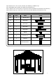
Parts List Part# Qty. Name A1 8 Gutter C1 8 Part# Qty.
Hardware Pack for STEP 1 Qty.
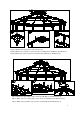
Fig.1: Attach Gutter (A1) to Post A3 & B3 with Bolt (g) and Washer (b). Fig.2: Attach Side panel C3-1(C3-2) to Post A3 & B3 with Bolt (h) and Washer (b). (Make sure the side with hole is outside) Fig.3: Two person set up the assembled post and another person raises Gutter (A1), the fourth person attaches (A1) to the assembled post with Bolt (g & a) and Flat washer (b). Assemble all gutters and tighten. Fig.4: Use Stake (j) to fasten the post to the ground if it is soft surface. Fig.
Fig.6: Attach Corner connector (B1) to Gutter (A1) with Bolt (i) and Washer (b). Fig.7: Attach Baffle (D3) to Gutter (A1) with Bolt (g) and Washer (b). Fig.8-1: Attach Corner connector (B1) to Large top roof bar (C1) with Bolt (d), Flat washer (b) and Nut (e). Fig.8-2: Attach Large top roof bar (C1) to Roof connection (D1) with Bolt (i) and Flat washer (b). Hardware Pack for STEP 2 Qty.
Fig.9-1: Attach Center hook (H1) to Top connector (J1). Fig.9-2: Attach Top roof bar (I1) to Top connector (J1) with Bolt (h), flat Washer (b) and Nut (e). Fig.10: Attach Top roof bar (I1) to Roof connection (D1) with Bolt (c), flat Washer (b). Fig.11: Attach Roof panel (B2) to Top roof bar (I1) with Bolt (c) and Flat washer (b). Fig 12: Attach Top roof covering (C2) to Top roof bar (I1) with Bolt (f) and Flat washer (b). Fig 13: Attach Top roof (D2) to Top connector (J1) with Nut (k) and Flat washer (l).
Fig.14-1: Attach Baffle 1 (H2) to Large roof panel 1(F2) with Bolt (i) and Flat washer (b). Back surface is labeled UP. Fig.14-2: Slide Large roof panel 2 (G2) under Large roof panel 1 (F2). Fig.14.3: Attach Baffle 2 (A2) to Large roof panel 2 (G2) with Bolt (i) and Flat washer (b). Fig.14.4: Attach Large roof panel 2 (G2) to the corner of Gutter (A1) with Bolt (c) and Flat washer (b). Fig.15-1: Insert Upper covering for large roof (I2) into the hole of Top roof bar (I1). Fig.
Hardware Pack for STEP 3 Qty. Part # Name 44 b M6 Flat washer 20 i M6*15 Bolt 24 n M6*25 Bolt Picture Fig.16-1: Attach Side panel (F3) to Planter box (E3) with Bolt (n) and Flat washer (b). Fig.16-2: Hang the assembled planter box on the Side panel 2 (C3-2).
Fig.17-1: Attach Top bracket (I3) to Side panel 1 (C3-1) with Bolt (i) and Flat washer (b); attach Slate table top (G3) to Top bracket (I3) at the same time. Fig.17-2: Attach Plate (H3) to Slate table top (G3) and Side panel 1 (C3-1) with Bolt (i) and Flat washer (b). Fig.18-1: Insert Short netting bar (T1) and Long netting bar (T2) into Connector (S1/S2). Fig.18-2: Attach Connector(S1/S2)to Baffle (D3). Spare Parts Qty.
IMPORTANT: 1. Keep all children and pets away from assembly area. Children and pets should be supervised when they are in the area of gazebo construction. 2. The area for assembly should not be less than 6 feet from any obstruction such as fence, garage, house, overhanging branches, laundry line or electrical wires. 3. This unit is heavy. Do not assemble this item alone. Six people are recommended for safe assembly. 4. Some parts may contain sharp edges. Wear protective gloves if necessary during assembly.
Maintenance: Our iron/steel components for garden accessories and patio items are coated with rust inhibiting paint that protects it from rusting. However, due to the nature of iron, surface oxidation (rusting) will occur once these protective coatings are scratched. This is a natural process and is not a defect! To minimize this condition, we recommend care when assembling & handling the product to prevent scratching the paint.
GAZEBO NETTING AND CURTAIN ASSEMBLY INSTRUCTIONS Netting / Curatin is available separately 12
Fig.19-1: Raise Connector Fig.19-2: Pull out Short netting (S2/S1) and take them down. Fig.20: Hang the five rings of curtain into bar (T1) and Long netting bar Short netting bar (T1) from right side, (T2) from Connector (S1/S2). then insert Short netting bar (T1) into Right connector (S2). Fig.21: Hang the other rings of curtain into adjacent Short netting bar (T1) from left side, assembled Fig.