
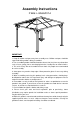
Installation Guide
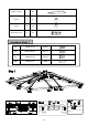

6 / 9
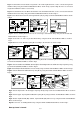
Fig.1: Insert Beam Connector Q into Long Beam 1 E1 and Long Beam 2 E2, secure connected long beam
and Bar 2 I2 by using Screw AA and Flat Washer BB as shown in Fig.1.(Notes: Align the holes of connected
long beam and Bar 2 I2 before secure them)
Fig.1-1: Insert Beam Connector Q into Short Beam 1 E3 and Short Beam 2 E4, secure connected short beam
and Beam Connector F2 by using Screw AA and Flat Washer BB as shown in Fig.1-1。
Fig.2: Secure Beam Connector F2 and Long Beam E1 (E2) by using Screw AA and Flat Washer BB as shown
in Fig.2
Fig.2-1: Secure Slanting Beam Connector F1 and Long & Short Beam E by using Screw AA and Flat
Washer BB as shown in Fig.2-1
Fig.3: Secure Bar 1 I1 and Long & Short Beam E by using Screw AA and Flat Washer BB as shown in
Fig.3.
Fig.4: Attach Hook N to Bottom Top Tray O1 according to the direction as shown in Fig.4
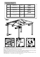
Fig.7: Secure Top Beam 1 M1 and Upper Top Tray O2 by using Screw CC and Flat Washer BB as shown in
Fig.7
Fig.8: Secure Upper Top Tray O2 and Bottom Top Tray O1 by using Screw CC and Flat Washer BB as shown in
Fig.8
Fig.9: Secure Top Beam M2 (M3) and M1, Top Beam M2 (M3) and Pole L by using Screw AA and Flat Washer
BB as shown in Fig.9
Fig.10: Lock Pole L to Slanting Beam G1 by using Screw AA and Flat Washer BB as shown in Fig.1.
Now top frame is formed.
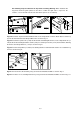
Fig.5: Secure the end with connect piece of Slanting Beam G1 and Slanting Beam Connector F1 by using
Screw CC and Flat Washer BB as shown in Fig.5
Fig.5-1: Secure another end without connect piece of Slanting Beam G1 and Bottom Top Tray O1 by using
Screw CC and Flat Washer BB as shown in Fig.5-1
Fig.6: Secure Beam G2 and Beam Connector F2 by using Screw CC and Flat Washer BB as shown in Fig.6
Fig.6-1: Secure Beam G2 and Bottom Top Tray O1 by using Screw CC and Flat Washer BB as shown in
Fig.6-1