
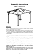
Installation Guide

8 / 9
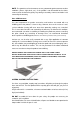
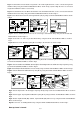
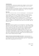
The following steps are about the PC Top Panel assembly. (Warning: When install the PC
top panel, follow the guide printed on the film to confirm the right side is exposed to the
sunshine , tear off the film on both sides after all the panels are assembled.)
Fig.14: Insert PC Top Panel 5 K5 into Beam G2, insert I-Shaped Bar 3 H3 into Beam G2, insert PC Top
Panel3 K3 into Beam G2 and I-Shaped Bar3 H3 as shown in Fig.14
Fig.15: Insert PC Top Panel K1 (or K2) into Beam G2 and Slanting Beam G1; insert I-Shaped Bar H1 (or
H2) into Bean G2, Slanting Beam G1 and K1(or K2); insert PC Top Panel K3 (or K4) into Beam G2, Slanting
Beam G1 and I-Shaped Bar H1 ( or H2) as shown in Fig.15
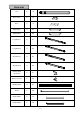
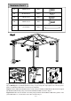
Fig.16: Insert F-Shaped Bar (J1,J2&J3) into Slanting Beam G1 and Beam G2 and the most sided PC Top
Panel as shown in Fig.16
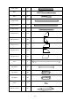
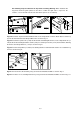
Fig.17: Fix Panel 2 P2 to Beam G2 by using Screw CC and Flat Washer BB as shown in Fig.17
Fig.17-1: Fix Panel 1 P1 to Slanting Beam G1 by using Screw CC and Flat Washer BB as shown in Fig.17-1