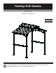
Hardtop Grill Gazebo ITEM #0757134 MODEL #L-GG030PST-B Français p. 12 Español p. 24 Questions, problems, missing parts? Before returning to your retailer, call our customer service department at 1-866-578-6569 anytime 24 hours / 7 days a week, or email to lowes@sunjoygroup.com or visit www.sunjoyonline.com.
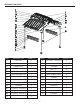
PACKAGE CONTENTS PART DESCRIPTION QUANTITY PART DESCRIPTION A Roof Vent 2 I2 Roof Cladding – short panel(2) 2 B Base 4 I3 Roof Cladding – short panel(3) 2 C Base cover 4 J Trim Cap 1 D1 Truss Beam (1) 2 K1 Post(1) D2 Truss Beam (2) 2 K2 Post(2) 2 2 E Top Connecting Pole 1 L Skew Support Piece 4 F1 Connecting Board 1 2 M1 Counter 2 F2 Connecting Board 2 2 M2 Tile 14 F3 Connecting Board 3 4 M3 Presser 1 24 G Top Hook 2 M4 Presser 2 8 H1 Roof Cl
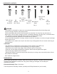
HARDWARE CONTENTS AA M6 x 20 mm Screw Qty. 80+8 BB CC DD II M6 x 15 mm Screw M6 x 35 mm M6 Washer Qty. 48+5 Screw Φ8*240 mm Stake Qty. 130+13 Qty. 2+1 Qty. 8 JJ M4 x 10 mm Screw Qty. 32+4 Z M6 Wrench Qty. 2 WARNING • This product is intended for outdoor use only and should be placed on flat, horizontal ground. • Ensure enough clearance around the product. • Before assembling the product, find level ground no less than 6 ft.
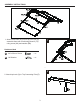
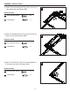
ASSEMBLY INSTRUCTIONS 1. Attach truss beam D1 (D2) to top roof vent (A), assemble them with Connecting Board 2 (F2) using screw (AA) and washer (BB). 1 F A Hardware Used AA M6 x 20 mm Screw x 12 BB M6 Washer x 12 BB D1 D2 AA F2 2 2. Attach top hook (G) to Top Connecting Pole (E).
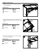
ASSEMBLY INSTRUCTIONS 3. Attach Top Connecting Pole (E) to top roof vent (A) using screw (AA) and washer (BB). 3 BB Hardware Used AA M6 x 20 mm Screw x4 BB M6 Washer x4 AA A BB E AA F2 4. Attach Connecting Board 3 (F3) to top roof vent (A) using screw (AA) and washer (BB). 4 A Hardware Used AA M6 x 20 mm Screw x8 BB M6 Washer x8 BB AA G D2 5. Attach Truss Beam D1 (D2) to Connecting Board 3 (F3) using screw (AA) and washer (BB).
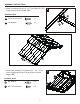
ASSEMBLY INSTRUCTIONS 6. Attach Connecting Board 1(F1) to Truss Beam D1 (D2) using screw (AA) and washer (BB). 6 K D2 ( D1 ) BB Hardware Used AA BB M6 x 20 mm Screw M6 Washer x8 BB x8 7 CC BB Hardware Used CC M6 Washer M6 x 15 mm Screw F1 AA 7. Attach Roof cladding – long panels (H1,H2,H3) to Cover Supporting Board (O) using screw (CC) and washer (BB).
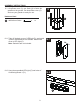
ASSEMBLY INSTRUCTIONS 8. Attach the Roof cladding – short panels (I1,I2,I3) to Cover Supporting Board (O) using screw (CC) and washer (BB). 8 Hardware Used BB M6 Washer x 16 CC M6 x 15 mm Screw x 16 9 I3 I2 BB 9. Attach trim cap (J) to Top Connecting Pole using screw (DD) and washer (BB). CC I1 CC BB Hardware Used BB M6 Washer x2 DD M6 x 35 mm Screw x2 DD BB DD J 10. Insert Base cover (C) into Pole (K1 & K2), attach Base (B) and Pole (K1 & K2) using screw (CC), washer (BB).
ASSEMBLY INSTRUCTIONS 11. Lift the assembled big top and insert the Posts (K1 & K2) into the Truss Beam (1) (D1) and Truss Beam (2) (D2), secure with screw (AA), washer (BB).
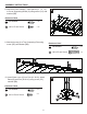
ASSEMBLY INSTRUCTIONS 12 . Attach Screen (N) to Pole (K1 & K2) using screw (AA), washer (BB). 12 Hardware Used AA M6 x 20 mm Screw x8 BB M6 Washer x8 N BB AA BB AA K1 & K2 13. Attach Skew support piece (L) onto Pole (K1 & K2) and Truss Beam (D1 & D2) using screw (AA), washer (BB). 13 AA D1 & D2 BB Hardware Used AA M6 x 20 mm Screw x 16 BB M6 Washer x 16 AA BB K1 & K2 14. Attach Countertop (M1) onto Pole (K1 & K2) using screw (AA), washer (BB).
ASSEMBLY INSTRUCTIONS 15. Lift up Base cover (C), use Stake (II) to fasten the gazebo on the ground. Put down Base cover (C) and now your gazebo is ready for use. Hardware Used II Φ8*240 mm Stake 15 II x8 16-1. Take off the back cover of LED light (P), and match 3 pieces AAA batteries into sockets. Attach back cover to LED light (P). Note : Batteries are not included. II C 16-1 Q P 16-2. Hang the assembled LED light (P) into holes of Connecting Board 1 (F1).
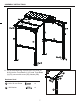
Preassemble Step: Insert the Tile (M2) into the pane of the counter (M1). Fasten the tile using Presser1 (M3), Presser2 (M4) and screw JJ. JJ JJ M4 JJ M3 M3 M2 M2 JJ JJ JJ M4 M1 Hardware Used JJ M4*10 mm Screw x 32 CARE & MAINTENANCE To extend the life of grill gazebo, do not use when there are high winds. Disassemble and pack away when the gazebo will not be used for an extended period.Ensure that the metal parts are all dry before packing away.
REPLACEMENT PARTS LIST For replacement parts, call our customer service department at 1-866-578-6569 anytime 24 hours / 7 days a week.
Gazebo Gril à Toit Solide ARTICLE #0757134 MODÈLE #L-GG030PST-B Des questions, des problèmes, des pièces manquantes? Avant de retourner l’article au détaillant, communiquez avec notre service à la clientèle au 1-866-578-6569 à n’importe quelle heure, ou envoyez un email à lowes@sunjoygroup.com ou visiter le www.sunjoyonline.com.
CONTENU DE L’EMBALLAGE PIÈCE DESCRIPTION QTÉ PIÈCE DESCRIPTION QTÉ A Façade du Petit Toit 2 I2 Panneau de Toiture Court (2) 2 B Base 4 I3 Panneau de Toiture Court (3) 2 Cuirasse 1 2 2 C Couvert de Base 4 J D1 Poutre Inclinée (1) 2 K1 Poteau(1) D2 Poutre Inclinée (2) 2 K2 Poteau(2) E Poutre de Connexion du Toit 1 L F1 Poutre Horizontale 1 2 M1 Comptoir 2 F2 Poutre Horizontale 2 2 M2 Carreau 14 F3 Poutre Horizontale 3 4 M3 Rondelle Carrée 1 24 G Croche
QUINCAILLERIE INCLUSE AA Visse M6 x 20 mm Qté. 80+8 BB Rondelle M6 CC DD JJ II Visse M4 x 10 mm Qté. 32+4 Visse M6 x 15 mm Visse Piquets Qté. 48+5M6 x 35 mm Φ8*240 mm Qté. 130+13 Qté. 2+1 Z Clé M6 Qté. 2 Qté. 8 AVERTISSEMENTS • Ce produit est conçu pour emploi extérieur uniquement et doit être installé sur une surface plate et horizontale. • Assurez-vous de laisser assez d’espace de dégagement autour de cet article.
INSTRUCTIONS POUR L’ASSEMBLAGE 1. Fixez la Poutre Inclinée D1 (D2) à la façade du toit (A), assemblez-les avec la Poutre Horizontale 2 (F2) avec boulon (AA) et rondelle (BB). 1 F A Quincaillerie utilisée AA Visse M6 x 20 mm x 12 BB Rondelle M6 x 12 BB D1 D2 2. Fixez le crochet du toit (G) à la poutre de connexion du toit (E).
INSTRUCTIONS POUR L’ASSEMBLAGE 3. Fixez la poutre de connexion du toit (E) à la façade du toit (A) avec boulon (AA) et rondelle (BB). 3 BB Quincaillerie utilisée AA Visse M6 x 20 mm x4 BB Rondelle M6 x4 AA A BB E AA F2 4. Fixez la Poutre Horizontale 3 (F3) à la façade du toit (A) avec boulon (AA) et rondelle (BB). 4 A Quincaillerie utilisée AA Visse M6 x 20 mm BB x8 AA G BB Rondelle M6 x8 D2 5.
INSTRUCTIONS POUR L’ASSEMBLAGE 6. Fixez la poutre horizontale 1(F1) à la poutre inclinée D1 (D2) avec boulon (AA) et rondelle (BB). 6 K D2 ( D1 ) BB Quincaillerie utilisée AA BB Visse M6 x 20 mm Rondelle M6 x8 BB x8 7 CC BB Quincaillerie utilisée CC Rondelle M6 Visse M6 x 15 mm F1 AA 7. Fixez les Panneaux de Toiture longs (H1 H2 H3) à la Barre de Support de la Toiture (O) avec boulon (CC) et rondelle (BB).
INSTRUCTIONS POUR L’ASSEMBLAGE 8. Fixez les Panneaux de toiture courts (I1 I2 I3) à la barre de Support de la Toiture (O) avec boulon (CC) et rondelle (BB) Quincaillerie utilisée Rondelle M6 x 16 CC Visse M6 x 15 mm x 16 CC I1 CC BB I3 I2 BB 9. Fixez la cuirasse (J) à la Poutre de Connexion du Toit avec boulon (DD) et rondelle (BB). 9 8 BB Quincaillerie utilisée BB Rondelle M6 x2 DD Visse M6 x 35 mm x2 DD BB DD J 10.
INSTRUCTIONS POUR L’ASSEMBLAGE 11. Soulevez le grand toit assemble et introduisez les Poteaux (K1 et K2) dans les Poutres Inclinées (1) (D1) et Poutres Inclinées (2) (D2), fixez avec Visse (AA), rondelle (BB).
INSTRUCTIONS POUR L’ASSEMBLAGE 12. Connectez la Façade (N) au Poteau (K1 et K2) avec boulon (AA), rondelle (BB). 12 Quincaillerie utilisée N AA Visse M6 x 20 mm x8 BB Rondelle M6 x8 BB AA BB AA K1 & K2 13. Connectez le Support de l’Angle (L) aux Poteaux (K1 et K2) et aux Poutre Inclinées (D1 et D2) avec boulon (AA), rondelle (BB). 13 AA D1 & D2 BB Quincaillerie utilisée AA Visse M6 x 20 mm x 16 BB Rondelle M6 x 16 AA BB K1 & K2 14.
INSTRUCTIONS POUR L’ASSEMBLAGE 15. Soulevez le Couvert de la Base (C), avec les Piquets (II), ancrez le gazebo à la terre. Rabaissez le Couvert de la Base (C) et maintenant votre gazebo est prêt à en profiter. Quincaillerie utilisée II Piquets Φ8*240 mm 15 II x8 16-1. Enlevez le couvert arrière de la Lampe LED (P), et introduisez 3 piles AAA dans leur espace correspondent. Revissez le Couvert Arrière de la lampe LED (P). Avis : Les piles ne sont pas comprises. II C 16-1 Q P 16-2.
Étape de Pré Montage : Introduisez les carreaux (M2) dans les cadres du comptoir (M1). Fixez les Rondelles Carrées 1 (M3), Rondelles Carrées2 (M4) et visses JJ. JJ JJ M4 JJ M3 M3 M2 M2 JJ JJ JJ M4 M1 Quincaillerie utilisée JJ Visse M4 x 10 mm x 32 SOIN ET ENTRETIEN Pour que votre gazebo gril dure plus longtemps, ne l’utilisez pas quand il y a du vent fort. Démontez-le et gardez le pendant des périodes longues de ne pas l’employer.
LISTE DE PIÈCES DE RECHANGE Pour pièces de rechange, veuillez appeler notre secteur de Service à la clientèle au 1-866-578-6569 à n’importe quelle heure.
Gazebo Parrilla con Techo Solido ARTÍCULO #0757134 MODELO #L-GG030PST-B Preguntas, problemas, piezas faltantes? Antes de volver a la tienda, llame a nuestro Departamento de Servicio al Cliente al 1-866-578-6569, da cualquier hora, o mande un correo E a lowes@sunjoygroup.como visite www.sunjoyonline.com.
CONTENIDO DEL PAQUETE PIEZE DESCRIPCIÓN CANTIDAD PIEZE DESCRIPCIÓN A Fachada del Techo Pequeño 2 I2 Panel de Techado Corto (2) 2 B Base 4 I3 Panel de Techado Corto (3) 2 C Cubierta de Base 4 J Moldura 1 D1 Viga Inclinada (1) 2 K1 Poste(1) D2 Viga Inclinada (2) 2 K2 Poste(2) 2 2 E Viga de Conexión del Techo 1 L Apoyo de Esquina 4 F1 Viga Horizontal 1 2 M1 Mostrador 2 F2 Viga Horizontal 2 2 M2 Azulejo 14 F3 Viga Horizontal 3 4 M3 Arandela Cuadrada 1 24
ADITAMENTOS AA Tornillo M6 x 20 mm Cant. 80+8 BB Arandela M6 CC DD JJ II Llave M4 x 10 mm Cant. 32+4 Tornillo M6 x 15 mm Tornillo Estacas Cant. 48+5 M6 x 35 mm Φ8*240 mm Cant. 130+13 Cant. 2+1 Z Llave M6 Cant. 2 Cant. 8 AVISOS • Este producto esta concebido par empleo al exterior únicamente y se debe instalar en una superficie plana y horizontal. • Asegúrese de dejar bastante espacio de distancia alrededor de este articulo.
INSTRUCCIONES DE ENSAMBLAJE 1. Fije la Viga Inclinada D1 (D2) a la fachada del techo (A), conéctelas a la Viga Horizontal 2 (F2) con tornillo (AA) y arandela (BB). 1 F A Aditamentos utilizados AA Tornillo M6 x 20 mm x 12 BB Arandela M6 x 12 BB D1 D2 2. Atornille el gancho del Techo (G) a la viga de conexión del techo (E).
INSTRUCCIONES DE ENSAMBLAJE 3. Fije la viga de conexión del techo (E) a la fachada del techo (A) con tornillo (AA) y arandela (BB). 3 BB Aditamentos utilizados AA Tornillo M6 x 20 mm x4 BB Arandela M6 x4 AA A BB E AA F2 4. Conecte la Viga Horizontal 3 (F3) a la fachada del techo (A) con tornillo (AA) y arandela (BB). 4 A Aditamentos utilizados AA Tornillo M6 x 20 mm x8 BB Arandela M6 x8 BB AA G D2 5.
INSTRUCCIONES DE ENSAMBLAJE 6. Fije la Viga Horizontal 1(F1) a la viga inclinada D1 (D2) con tornillo (AA) y arandela (BB). 6 K D2 ( D1 ) BB Aditamentos utilizados AA Tornillo M6 x 20 mm x8 BB Arandela M6 x8 BB 7 CC BB Aditamentos utilizados Arandela M6 x 24 CC Tornillo M6 x 15 mm x 24 F1 AA 7. Fije los Paneles de Techado largos (H1 H2 H3) a la Barra de Apoyo del Techado (O) con Tornillo (CC) y arandela (BB).
INSTRUCCIONES DE ENSAMBLAJE 8. Fije los Paneles de Techado cortos (I1 I2 I3) a la Barra de Apoyo del Techado (O) con tornillo (CC) y arandela (BB). 8 Aditamentos utilizados CC BB Arandela M6 x 16 CC Tornillo M6 x 15 mm x 16 9 I3 I2 BB 9. Fije la moldura (J) a la Viga de Conexión del Techo con tornillo (DD) y arandela (BB). CC I1 BB Aditamentos utilizados BB Arandela M6 x2 DD Tornillo M6 x 35 mm x2 DD BB DD J 10.
INSTRUCCIONES DE ENSAMBLAJE 11. Levante el montaje del techo grande e introduzca los Postes (K1 et K2) en las Vigas Inclinadas (1) (D1) y las Vigas Inclinadas (2) (D2), fije con un Tornillo (AA), y arandela (BB).
INSTRUCCIONES DE ENSAMBLAJE 12. Conecte la Fachada (N) al Poste (K1 y K2) con tornillo (AA), y arandela (BB). 12 Aditamentos utilizados AA BB Tornillo M6 x 20 mm Arandela M6 N x8 BB AA x8 BB AA K1 & K2 13. Conecte el Apoyo de Esquina (L) a los Postes (K1 et K2) y a las Vigas Inclinadas (D1 y D2) con tornillo (AA), y arandela (BB). 13 AA D1 & D2 BB Aditamentos utilizados AA BB Tornillo M6 x 20 mm Arandela M6 x 16 AA x 16 BB K1 & K2 14.
INSTRUCCIONES DE ENSAMBLAJE 15. Levante la Cubierta de la Base (C), y con las Estacas (II), ancle el gazebo a la tierra. Vuelva a bajar la Cubierta de la Base (C) y ahora Su Gazebo está listo para disfrutarlo. Aditamentos utilizados II Estacas Φ8*240 mm 15 II x8 16-1. Quite la tapadera trasera de la lámpara LED (P), e instale 3 pilas AAA en su lugar adecuado. Vuelva a instalar la tapadera trasera de la lámpara LED (P). Aviso: Las pilas AAA no están incluidas. II C 16-1 Q P 16-2.
Etapa de Pre montaje : Introduzca los Azulejos (M2) en los marcos del Mostrador (M1). Fije los Azulejos con las Arandelas Cuadradas1 (M3), Arandelas cuadradas 2 (M4) y Tornillos JJ. JJ JJ M4 JJ M3 M3 M2 M2 JJ JJ JJ M4 M1 Aditamentos utilizados JJ Llave M4 x 10 mm x 32 CUIDADO Y MANTENIMIENTO Para que vuestro gazebo parrilla dure más tiempo, no lo utilice cuando hay vientos fuertes. Desmóntelo y guárdelo si no lo va a utilizar durante un tiempo largo.
LISTA DE PIEZAS DE RECAMBIO Para piezas de recambio, llame por favor a nuestra sección de Servicio al Cliente al 1-866-578-6569 a cualquier hora.