AQ09VFU Series AQ12VFU Series AQ18VFU Series AQ24VFU Series AQ36VFU Series Air Conditioner user & installation manual imagine the possibilities Thank you for purchasing this Samsung product. To receive more complete service, please register your product at www.samsung.com/register E S F DB98-32163A-2 Vivaldi MAX_AQN09VFU@@ IB&IM_32163A_E.
Features of your new air conditioner Cool Summer Offer On those hot sweltering summer days and long restless nights, there is no better escape from the heat than the cool comforts of home. Your new air conditioner brings an end to exhausting hot summer days and lets you rest. Beat the heat with your own air conditioner this summer.
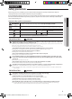
USING PARTS Safety precautions Before using your new air conditioner, please read this manual thoroughly to ensure that you know how to safely and efficiently operate the extensive features and functions of your new appliance. Important safety symbols and precautions: WARNING Hazards or unsafe practices that may result in severe personal injury or death. CAUTION Hazards or unsafe practices that may result in minor personal injury or property damage. Follow directions.
Safety precautions FOR POWER SUPPLY WARNING Remove all foreign substances such as dust or water from the power plug terminals and contact points using a dry cloth on a regular basis. Unplug the power plug and clean it with a dry cloth. Failing to do so may result in electric shock or fire. Plug the power plug into the wall socket in the right direction so that the cord runs towards the floor.
FOR USING WARNING ENGLISH Do not place an object near the outdoor unit that allows children to climb onto the machine. This may result in children seriously injuring themselves. Do not use this air conditioner for long periods of time in badly ventilated locations or near infirm people. Since this may be dangerous due to a lack of oxygen, Open a window at least once an hour.
Checking before use Operation ranges The table below indicates the temperature and humidity ranges the air conditioner can be operated within. Refer to the table for efficient use.
Checking the name of the parts Your air conditioner may slightly look different from illustration shown above depending on your model. Main parts ENGLISH Room temperature sensor Air intake Air filter(under the panel) Air flow blade (up and down) Blade pin lever Air flow blade (left and right) Display Remote control receiver Operation indicator Timer indicator Smart Saver indicator Power button 7 Vivaldi MAX_AQN09VFU@@ IB&IM_32163A_E.
Checking the remote controller • Point the remote controller towards the remote controller receiver of the indoor unit. • When you properly press the button on the remote controller, you will hear beep sound from the indoor unit and a transmit indicator( ) appears on the remote controller display. Remote controller buttons Smart Saver Less energy usage makes your space cool between the temperature range of 76°F ~ 86°F(24°C~30°C). Turbo Operate in auto fan speed to cool quickly.
Remote controller display On Timer indicator Off Timer indicator indicator ENGLISH Turbo indicator Quiet indicator Smart Saver indicator Operation mode indicator Low battery indicator Transmit indicator Air swing indicator Fan speed indicator Auto (Turbo) Low Medium High Battery changing time When the battery is exhausted, ( ) will be displayed in the remote controller display. When the icon appears, change the batteries. The remote controller requires two 1.5V AAA type batteries.
Basic function Basic operation is an operation mode that can be selected by pressing the Mode button. Auto In Auto mode, the air conditioner will automatically set the temperature and fan speed depending on the room temperature detected by the room temperature. Cool In Cool mode, the air conditioner will cool your room. You can adjust the temperature and the fan speed to feel cooler in hot season.
Press the button to turn on the air conditioner. Press the button to set the operating mode. ENGLISH • Each time you press the Mode button, the mode will change in order of Auto, Cool, Dry, Fan and Heat. Press the button to set the desired fan speed. Auto (Auto) Cool (Auto), Dry Fan Heat Press the (Low), (Med), (High) (Auto) (Low), (Auto), (Med), (Low), (High) (Med), (High) button to adjust the temperature.
Adjusting the air flow direction Air flow can be directed to your desired position. Vertical air flow Air flow blades move up and down. Press the Air swing button on the remote controller. Air swing indicator will be on and air flow blades move up and down continuously to circulate the air. Press the Air swing button on the remote controller again, to keep the air flow direction in a constant position.
mode For a comfortable sleep, the air conditioner will operate it Fall asleep Sound sleep Wake up from mode. When the air conditioner is on and in cool/heat mode button on the remote controller. indicator appears and Off timer indicator starts blinking on the remote controller display. ENGLISH 1. Press the 2. Press the Time Up or Time Down button to set the time. You can set the time in half hourly unit from 30 minutes ~ 3 hours and hour unit from 3 hours ~ 12 hours.
Setting the On/Off timer You can set the air conditioner to turn on/off automatically at desired time. Setting On timer while the air conditioner is off / Off timer while the air conditioner is on Setting On timer 1. Press the On Timer/Off Timer button. On/Off timer indicator will blink on the remote controller display. 2. Press the Time Up or Time Down button to set the time. You can set the time in half hourly unit from 30 minutes ~ 3 hours and hour unit from 3 hours ~ 24 hours.
Combining On Timer and Off Timer If the air conditioner is on If the air conditioner is off Preset time on On timer is shorter than Off timer Ex) On timer : 3 hours, Off timer : 5 hours - The air conditioner will operate On timer after 3 hours from the moment you have set the timer. Your air conditioner will remain on for 2 hours and then turn off automatically.
Using the Quiet function You can reduce the noise generated from an indoor unit. Press the Quiet button on the remote controller while the air conditioner is operating in Cool/Heat mode. Quiet indicator appears on the remote controller display. The indoor unit will operate more quietly. Cancel Press the Quiet button once again. • I f using a multi system, this function will work only when the Quiet function is set on all operated indoor units.
Cleaning the air conditioner • Make sure the power is turned off and unplugged from the wall socket when cleaning the air conditioner. ENGLISH Cleaning the indoor unit Wipe the surface of the unit with a slightly wet or dry cloth when needed. • C ontact the service center when you clean the indoor unit heat exchanger because it needs to be disassembled. • D o not clean the display using alkaline detergent.
Cleaning the air conditioner Removing the Air filter Grab the handle and lift it up. Then, pull the Air filter towards you and slide it down. Air filter Cleaning the air filter Washable foam based air filter captures large particles from the air. The filter is cleaned with a vacuum or by hand washing. Open the panel and put the Air filter out. Clean the Air filter with a vacuum cleaner or soft brush. If dust is too heavy, rinse it with running water.
Maintaining the air conditioner If the air conditioner will not be used for an extended period of time, dry the air conditioner to maintain it in best condition. 2. Before using the air conditioner again, dry the inner components of the air conditioner again by running in Fan mode for 3 to 4 hours. This helps remove odors which may have generated from dampness. ENGLISH 1. Dry the air conditioner thoroughly by operating in Fan mode for 3 to 4 hours and disconnect the power plug.
Troubleshooting Refer to the following chart if the air conditioner operates abnormally. This may save time and unnecessary expenses. PROBLEM SOLUTION The air conditioner does not work at all. • Check power status and then operate the air conditioner again. • Plug in or switch on the circuit breaker and then operate the air conditioner again. • Check if you have set the Off Timer. Operate the air conditioner again by pressing the Power button. The temperature adjustment is not working.
SOLUTION Error is indicated. • When an indoor unit indicator blinks, contact the nearest service center. Noise is generated. • D epending on the status of the air conditioner usage, noise can be heard when refrigerant flow movement changes. It is normal. Smoke is generated from the outdoor unit. • I f may not be a fire but it can be a steam generated by the defrost operation from outdoor heat exchanger during Heat mode in winter. Water is dropping from the outdoor unit piping connection.
INSTALLATION PARTS ※ In this manual, you may find model names written in simplified forms as indicated in following table. Model Names AQVFU 09 12 18 24 36 Included Models Remark AQ09VFU, AQ12VFU, AQ18VFU, AQ24VFU, AQ36VFU Grouping was done by series. AQ09VFU AQ12VFU AQ18VFU Grouping was done by capacity. AQ24VFU AQ36VFU Safety precautions Carefully follow the precautions listed below because they are essential to guarantee the safety of the equipment.
Installing the unit IMPORTANT: When installing the unit, always remember to connect first the refrigerant tubes, then the electrical lines. Always disassemble the electric lines before the refrigerant tubes. Upon receipt, inspect the product to verify that it has not been damaged during transport.
Choosing the installation location Outdoor Unit Where it is not exposed to strong wind Well ventilated and dustless places Out of the direct sunlight and rain Where neighbors are not annoyed by operation sound or hot air Solid wall or support that prevents vibration and is strong enough to hold the product weight Where there is no risk of flammable gas leakage When installing the unit at a high place be sure to fix the unit legs 9.
Space Requirements for Outdoor Unit When installing 1 outdoor unit ENGLISH Figure Description Top view Side view Air intake Air outlet Air intake Air outlet , Air flow direction. (Unit : inch) 59.1 or more When 3 sides of the outdoor unit are blocked by the wall 11.8 or more When the air outlet is towards the wall 11.8 or more When the air outlet is opposite the wall 5.
Choosing the installation location When front and rear side of the outdoor unit is towards the wall 59.1 or more 23.6 or more 118.1 or more 118.1 or more 19.7 or more 23.6 or more 59.1 or more 23.6 or more (Unit : inch) When the upper part of the outdoor unit and the air outlet is opposite the wall 19.7 or more 11.8 or more When the walls are blocking front and the rear side of the outdoor units 11.8 or more 11.8 or more 7.
Optional accessories The following connection accessories are optional. If they are not supplied, you should obtain them before installing the air conditioner. Rubber Legs (4) Pipe Clamps A (3) Pipe Clamps B (3) Foam Insulation(1) Wired remote controller (1) Sub COMM PBA Cement Nails (6) Vinyl Tapes (2) Drain Plug (1) ENGLISH Insulated Insulated Assembly Pipe, Insulated Assembly Pipe, Insulated Assembly Pipe, PE T3 Foam Tube Assembly Pipe, Ø1/4inch (Ø6.35mm) Ø3/8inch(9.52mm) (1) Ø 1/2inch(12.
Fixing the installation plate 2. Fix the indoor unit. If you fix the indoor unit on a wall (1) Fix the installation plate to the wall giving attention to the weight of the indoor unit. Plastic Anchor • I f you mount the plate to a concrete wall using plastic anchors, make sure that gaps between the wall and the plate, created by projected anchor, is less than 0.79inch(20mm). Wall <0.
There must be no space between the terminal and the screw when connected. - Any remaining space may become a fire hazard due to overheating of the electrical contact. ENGLISH Either the screw is not fitted properly The terminal socket or there is a space between the screw is upside down. and the ring terminal. • F or the terminal block wiring, use a wire with a ring terminal socket only.
Connecting the assembly cable • End of the wire must be circular. • After connecting the cables, make sure terminal numbers on the indoor/outdoor unit matches. • Screws on terminal block must not be unscrewed with the torque less than 0.87ft•lb(12kgf•cm). 10. Connect the grounding conductor to the grounding terminals. 11. Close the terminal board cover by tightening the screw carefully. • I n Russia and Europe, consult with the supply authority to determine the supply system impedance before installation.
4. Cut off the remaining foam insulation. 5. If necessary, bend the pipe to fit along the bottom of the indoor unit. Then pull it out through the appropriate hole. The pipe should not project from the rear of the indoor unit. The bending radius should be 3.94inch(100 mm) or more. ENGLISH 6. Pass the pipe through the hole in the wall. 7. For further details on how to connect to the outdoor unit and purge the air, refer to page 35~37.
Cutting or extending the pipe 1. Make sure that you have all the required tools (pipe cutter, reamer, flaring tool and pipe holder). 2. If you want to shorten the pipe, cut it using a pipe cutter, ensuring that the cut edge remains at 90° with the side of the pipe (see below examples of correct and incorrect cut edges). Pipe cutter Oblique Rough Burr Pipe 3. To prevent a gas leak, remove all burrs at the cut edge of the pipe using a reamer.
Installing and connecting the drain hose of the indoor unit When installing the drain hose for the indoor unit, check if condensation draining is adequate. When passing the drain hose through the 2.56inch(65mm) hole drilled in the wall, check the followings: Wall ENGLISH Indoor unit Drain hose The drain hose must NOT slant upwards. The end of the drain hose must NOT be placed under water. 2inch (50mm) less The drain hose must not be bent.
Installing and connecting the drain hose of the indoor unit • T he hose will be fixed permanently into position after finishing the installation and the gas leak test; refer to page 39 for further details. • M ake sure the installed direction of the drain hose is correct. Inadequate installation may cause condensate water leakage. • If the drain hose is routed inside the room, insulate the hose so that dripping condensation does not damage the furniture or floors.
Installing and connecting the drain hose of the outdoor unit While heating, ice may accumulate. During the process of defrosting, check if condensation draining is adequate. For adequate draining, do the following: 1. Insert the drain plug into the drain hole on the underside of the outdoor unit. ENGLISH • T o avoid drain plug from contacting the ground, secure gap between the ground and the bottom surface of the outdoor unit. Drain hole Drain plug Bottom surface of outdoor unit 2.
Purging the connected pipes Outer Diameter • Excessive torque can be cause of gas leakage. • M ake the electrical connection and leave the system into “stand by mode”. Do not turn on the system! This is necessary for better vacuum operation (full OPEN position of Electronic Expansion Valve - EEV -). 3. Connect the charging hose of the low-pressure side of manifold gauge to a gas service port as seen in the picture. 4. Open the valve of the low pressure side of manifold gauge counterclockwise. 5.
Important information regulation regarding the refrigerant used 1. Please fill in with indelible ink, the factory refrigerant charge of the product, the additional refrigerant amount charged in the field and + the total refrigerant charge. on the refrigerant charge label Refrigerant type R410A GWP value 1975 ENGLISH This product contains fluorinated greenhouse gases covered by the Kyoto Protocol. Do not vent gases into the atmosphere.
Performing the gas leak tests AA Make sure to check for gas leaks before completing the installation process (connecting the assembly pipe and hose between indoor unit and outdoor unit, insulating the cables, hose and pipe, and fixing the indoor unit to the installation plate). A C D B To check for gas leaks on the outdoor unit, Check the valve A and B using a leak detector. To check for gas leaks on the indoor unit, Check the flare nut C and D using a leak detector.
Fixing AA the indoor unit in place Perform the following work on the area where gas leak test was done priorly. After checking for gas leaks in the system, insulate the pipe, hose and cables. Then place the indoor unit on the installation plate. Insulation ENGLISH 1. To avoid condensation problems, wrap foam insulation (as shown in the figure) on a part without insulation on the end of the pipes. Pipes 2. Wind the pipe, assembly cable and drain hose with vinyl tape. 3.
Final AA Check and Trial Operation To complete the installation, perform the following checks and tests to ensure that the air conditioner operates correctly. Check the followings: • Strength of the installation site • Tightness of pipe connection to detect gas leak • Electric wiring connection • Heat-resistant insulation of the pipe • Drainage • Grounding conductor connection • Correct operation (follow the steps below) 1.
How AA to connect your extended power cables Items to prepare (compressor and insulation tape should be prepared by an installation technician.) Tools Connection sleeve Insulation tape Contraction tube (mm) MH-14 0.79xØ0.28inch ((20xØ7.0mm)(HxOD) Width 0.71inch(18mm) 1.97x Ø0.31inch (50xØ8.0mm)(LxOD) ENGLISH Spec Crimping plier Shape 1. As shown in the figure, peel off the shields from the rubber/wire of the power cable. - Peel off 0.
Sub PCB installation(optional) (Wried remote controller, central remote controller etc.) 1. Turn the power off and tightly grab top of the front panel and pull it down to open. Then slightly lift the panel up. 2. Take off the Cover PCB, remove the Flocked. 3. Attach the Sub PCB to the right side of the Panel-frame. 09/12/18/24 Cover PCB Flocked 36 Cover PCB 4. Find the PCB wire, and connect the wire to the Sub PCB as seen in the picture. 09/12/18/24 Sub PCB 5.
Remocon module installation (optional) Components parts RAC-SUB PBA Haness Wire(for Wired Remocon) Wire Joint Quantity 1EA 1EA 4EA DB93-13561A DB93-11405A DB96-90020A ENGLISH Product name Shape Code Description RAC MAIN -SUB Connection External controller connection (MIM-B14) Wired Remocon (1,2 : 12V / 4,5 : COM2) (Single model doesn't use this function.
QUESTIONS OR COMMENTS? COUNTRY CALL CANADA 1-800-SAMSUNG(726-7864) MEXICO 01-800-SAMSUNG(726-7864) OR VISIT US ONLINE AT www.samsung.com/ca www.samsung.com/ca_fr (French) www.samsung.com U.S.A 1-800-SAMSUNG(726-7864) www.samsung.com ARGENTINE www.samsung.com Bolivia 0800-333-3733 0800-124-421 4004-0000 800-SAMSUNG(726-7864) From mobile 02-482 82 00 800-10-7260 COLOMBIA 01-8000112112 www.samsung.com COSTA RICA 0-800-507-7267 www.samsung.com DOMINICA 1-800-751-2676 www.samsung.