SUNNEX MEDICALIGHT © INSTALLATION & OPERATING MANUAL Celestial Star CS2050M (Mobile) CS2050C (Ceiling) CS2050W (Wall) CS2050D (Dual) WWW.SUNNEXMEDICAL.
Dear Customer: We appreciate that you have chosen to purchase a Sunnex Medical product and believe that it will fulfill your expectations. Sunnex takes great pride in our products which have been designed and manufactured in accordance with our strict ISO 9001 certified quality system, UL and CE electrical standards and, if applicable, the United States Food and Drug Administration’s regulations.
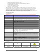
CONTENTS 1. Introduction ………………………………………..……………….. 3 1.1 Contents and Packaging 1.2 About the Light 2. Technical Description ……………………………..………………… 5 2.1 Technical Data 2.2 Symbols 2.3 Main Components and Dimensions 3. Customer Responsibilities …………………………………………… 7 4. Pre-wiring Instructions……………………………………………… 8 4.1 Standard Receptacle Installations 4.2 Hard-wire to Junction Box 5. Installation Instructions ……………………………………………… Ceiling Light…………………………………………………………… 5.1 Pre-installation Instructions 5.
1. Introduction 1.
Packaging Checklist CONTENTS CEILING BALANCE ARM ASSEMBLY CEILING ARM & TRANSFORMER ASSEMBLY BOX CONTAINING - ONE (1) SET OF DOME COVERS (LEFT & RIGHT) - ONE (1) SEISMIC BRACKET DUAL U ARM & TRANSFORMER ASSEMBLY WALL BOARD VERTICAL POLE ARM & TRANSFORMER ASSEMBLY CASTER BASE WITH WHEELS COUNTER BALANCE DUAL CEILING WALL MOBILE 1 1 2 2 1 1 0 1 0 0 0 0 0 0 0 0 1 1 0 0 0 1 0 0 1 2 0 1 1 1 1 1 2 2 1 1 1 1 2 3 4 6 2 3 2 3 - ALLEN WRENCH – 5/32 1 2 1 1 - 4 8 4 0 0 0 0 0 1
• Patented Lamp Shade reduces heat output • Unparalleled Flexibility with Extensive Reach and Range of Motion • Drift Free Balance Arm Design • Quick & Easy Bulb Replacement • Removable Sterilizable Handle This manual will assist you in assembling your light, introduce some of its most important and prominent features, and provide suggestions for its care. The light is intended for use in medical specialty environments where illumination is required for various medical examinations and procedures.
2.3 Main Components and Dimensions Figure 1. Ceiling Figure 3. Mobile (120V Model) Figure 2.
3. Customer Responsibilities Sunnex lights are built to provide exceptional illumination and should impart you with years of reliable service. Please follow the list below of installation criteria to ensure proper steps are taken prior to the mounting of the fixture, and help ensure its appropriate use.
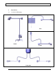
4. Pre-wiring Instructions 4.1 Standard Receptacle Installations Standard models are designed to be used with standard hospital grade 3 prong grounded outlet (receptacle) boxes. No modification or pre-wire is required. 4.2 Hard-wire to Junction Box The hard-wiring instructions apply to following models only: 1. CS2050C-HW (Ceiling, 120V) 2. CS2050W-HW (Wall, 120V) 3. CS2050CE-HW (Ceiling, 230V) 4.
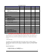
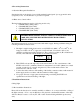
Refer to Figures 8, 9 & 10 and Table 1 for mounting heights and appendix A for hole pattern of the transformer housing and optional brackets & plates. 1. NEVER attempt to affix a ceiling light directly to a drop (false) ceiling, as many are not designed to withstand the weight requirements of the lighting systems, and may result in damage to the ceiling, the lighting unit or both. Additionally this may present a situation where failure may present a hazard to persons, resulting in injury. 2.
6. The contractor assumes the ultimate responsibility for the stability and strength of the final mounted fixture. MOUNTING TO A HORIZONTAL SURFACE An L-bracket can be used to secure the transformer housing to vertical plane above the drop (false) ceiling. Please refer to the dimensions of the optional bracket in appendix A. Seismic steel bracket can be used to secure the transformer housing to solid ceiling surface or cement ceiling surface. Minimum ½” (1.
Table 1 Guideline for ceiling style mount (Refers to Figures 8, 9 & 10) CEILING LIGHT MOUNTING INSTRUCTIONS WITH STANDARD EXTENSION Z-ARM TO ACHIEVE FLOOR TO LIGHT DISTANCE OF “A” IF DROP CEILING IS “B” 75 INCHES (1905 mm) (2440 mm) 86 INCHES (2184 mm) (2740 mm) 8.0 FEET 9.0 FEET MOUNT BOTTOM OF TRANSFORMER BRACKET FROM FLOOR AT “C” GAP BETWEEN DROP CEILING AND CEILING ARM “D” MINIMUM 2” REQUIRED 99.8 INCHES (2535 mm) 6.5” (165mm) 109.8 INCHES (2789 mm) 4.
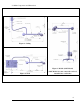
2.25”” L-BRACKET NOT INCLUDED D GAP Figure 8.
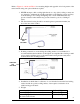
7 FEET 1 INCH 6 FEET 1 INCH 5 FEET 1 INCH Figure 9. Ceiling light (Standard arm) 8 FEET 4 INCHES 7 FEET 4 INCHES 6 FEET 4 INCHES Figure 10.
5.2 Installation Instructions 1. Slide transformer housing covers off of transformer brackets and set aside for future installation. 2. Follow Table 1 and Figures 8, 9 & 10 to determine the location of installation. 3. Fasten the transformer housing to the desired location using four (4) 3/8” or M10 bolts (not provided). The type of bolt will be dependent on your installation. These bolts may need to be either lag or machine bolts. Minimum lag bolt length is 2-1/4” or 60mm.
counter sunk holes on this end of the balance arm. Position the counter weight on the opposite side of the counter sunk holes on the balance arm. Set the (2) flat head screws (1/4-20” X 1/2”) supplied hex screws in the counter sunk holes and tighten them down using provided (5/32”) Allen wrench. Inset 3.0 (Figure 8) 8. Insert the sterilizable handle onto the mounting screw in the center of the lamp head and rotate clockwise to tighten. 9. Plug the hospital grade plug into the outlet.
3. with each light) can then be used to cover the hole in the drop ceiling created for the extension arms. The dimensions and recommended installation heights are identical to the single ceiling arm. 5.4 Installation Instructions (Ceiling Dual Light) 1. Follow instructions in sections 5.1 and 5.2 to complete installation of lights to ceiling. Figure 11 2. 3. If using dual mount seismic bracket, securely fasten dual mount seismic bracket to a structural member in the ceiling.
64.875” (165cm) floor to bottom of wall board 75” (190cm) Figure 13 3. Measure and mark on the wall board two vertical lines for three lag bolts, right and left of the wall board. Drill three holes on each line, approximately the size of the lag bolts chosen for mounting. RECOMMENDATION: LAG BOLTS OF AT LEAST 1/4” X 5” (M8 X 130mm) LONG, WITH WASHERS, SHOULD BE USED. BE SURE TO DRILL APPROPRIATE PILOT HOLES OF ADEQUATE DEPTH TO AVOID BREAKING THE BOLTS.
Supplied high density wall board Dry wall Edge distance (any edge) 1-1/2” (19mm) minimum Wood or metal stud 1/4” X 5” (M6X13cm) long steel hex head lag bolts. Minimum 6 required The bracket is secured to the wall board. 4 x 3/8” (M10) bolts. CAUTION! Do not use lag bolts if wall studs are metal. Appropriate fasteners must be utilized. Figure 14 4. Place the wall board in position and secure through the wall to the wooden wall studs, using six lag bolts.
6. Operating Instructions 1. After successful assembly of your light, plug the Hospital Grade plug into an appropriate Hospital Grade outlet. Do not use three-to-two prong adapters that are not grounded. 2. Turn on your light with the rocker switch in the back cover of the lamp head. (If a wall switch is also in use, be sure to have the rocker switch to off position before turning the wall switch on.) CAUTION: IF A WALL DIMMER IS USED WITH THE LIGHT, IT VOIDS CERTIFICATION LISTING OF THE PRODUCT.
CAUTION! DO NOT FORCE MOVEMENT PAST ITS STOP POSITION. Figure 18 Ceiling Light (Ranges of Motion) 7. Maintenance While your lamp light has been designed to provide you many hours of professional performance, it will benefit from your periodic care and concern. 7.1 Cleaning and Disinfection • The covers and frame may easily be cleaned with a soft damp cloth of a mild soap water solution or mineral spirits. • Isopropyl alcohol is another acceptable cleansing agent.
1. A flash cycle at 275 – 279O F (135 – 137O C), for 16 minutes 2. A standard cycle at 275 – 279O F (135 – 137O C), for 4 minutes 7.3 Bulb Replacement CAUTION: ONLY USE OSRAM/SYLVANIA TRU-AIM TITAN BULBS (DICHROIC, 12V/35W/10°), ANY DEVIATION FROM THESE INSTRUCTIONS MAY SERIOUSLY DAMAGE YOUR LIGHT. 35WATTS IS MAXIMUM ALLOWABLE. Should you experience a bulb failure, ALLOW SUFFICIENT TIME FOR IT TO COOL BEFORE ATTEMPTING A REPLACEMENT. Once cool, you should: 1. Refer to figures 19, 20 & 21.
Figure 19. Bulb Replacement - 1 ROTATE COUNTER-CLOCKWISE Figure 20. Bulb Replacement - 2 Figure 21. Bulb Replacement - 3 7.4 Fuse Replacement 1. Refer to figures 22 & 23. Remove the plug from outlet. 2. Locate two fuse blocks. Ceiling and Wall Models: Unscrew the plastic screws from transformer cover. Take off the transformer cover. Locate fuse holders (2) inside the transformer housing. Mobile Models: Locate two fuse blocks on the bottom of the transformer housing. 3.
MUST USE A SLOW-BLOW FUSE b. Europe: Sunnex part# 18641 (1.25 AMP, 250V, 5mm X 20mm) MUST USE A SLOW-BLOW FUSE Figure 22 Ceiling/Wall Fuse location Figure 23 Mobile Fuse location 8. Warranty 8.1 Limited Warranty. Sunnex warrants that the Product, if properly used, will be free from defects in material and workmanship, for a period of three (3) years from the date of shipment to Customer. This Limited Warranty extends only to the original buyer.
MERCHANTABILITY AND FITNESS FOR A PARTICULAR PURPOSE, REGARDLESS OF WHETHER SUNNEX KNOWS OR HAS REASON TO KNOW OF CUSTOMER’S PARTICULAR NEEDS. IF IMPLIED WARRANTIES MAY NOT BE DISCLAIMED UNDER APPLICABLE LAW, THEN ANY IMPLIED WARRANTIES THAT MAY BE IMPOSED BY LAW ARE LIMITED IN DURATION TO THE LIMITED WARRANTY PERIOD SET FORTH HEREIN, AND THEREAFTER ANY IMPLIED WARRANTIES ARE EXPRESSLY DISCLAIMED.
(e) Sunnex will ship the repaired Product or a replacement to Customer within ten (10) business days after receipt from the date that Sunnex receives the Product. Standard shipments to the Customer will be paid by Sunnex. Sunnex assumes no responsibility for shipment delays by the carrier. (f) If Customer requires warranty service to be provided in less than ten (10) business days, but not less than three (3) business days, Sunnex will charge Customer an additional One Hundred Dollars ($100.
9.
10.
Appendix B: OPTIONAL STEEL STRUCTURE PART# 18750 HORIZONTAL PLATE (OPTIONAL, TO BE PURCHASED SEPARATELY) 28 INSTALLATION AND OPERATING MANUAL
APPENDIX C: DUAL MOUNT SEISMIC BRACKET PART# 18523 OR 4 X 0.
PRODUCT SPECIFICATIONS SUBJECT TO CHANGE WITHOUT NOTICE 30 INSTALLATION AND OPERATING MANUAL
WWW.SUNNEXMEDICAL.COM Sunnex is certified ISO 9001:2008 by _______________________________________________________________________ Sunnex, Inc. 3 Huron Drive Natick, MA 01760-1314 USA Tel: + 1 800 445 7869 Fax: 1 508 651 0099 Email: sales@sunnex.com Sunnex Equipment AB Box 8064 SE-163 08 Spånga Sweden Tel: + 46 8 546 802 30 Fax: + 46 8 546 802 59 Email: info@sunnex.se Sunnex Equipment Sarl Zl. Les Milles B.P.