Table of Contents 1. SHIPPING CARTON & CONTENTS ..............................................................................4 2. INTRODUCTION ............................................................................................................5 3. CELESTIAL STAR MRI SPECIFICATIONS...................................................................6 3.1 TECHNICAL DATA ......................................................................................................6 3.2 EMC COMPATIBILITY ........
8. MARKINGS ..................................................................................................................29 9. WARRANTY .................................................................................................................34 10. TROUBLESHOOTING................................................................................................35 11. APPENDIX…………………………………………………………………………………...
This manual covers following models: CS2050M-MRI, CS2050C-MRI, CS2050D-MRI, CS2050C-MRI-HW, CS2050CE-MRI-HW CS2050D-MRI-HW, CS2050DE-MRI-HW 1.
2. INTRODUCTION The objective of this manual is to assist you in assembling your Celestial Star MRI light, to introduce some of its most important features, and to provide suggestions for its care. 2.1 INTENDED USE The Sunnex Celestial Star MRI light is intended for use in MRI environments where illumination is required for medical procedures. CAUTION! This light is intended for out of bore procedures only. Any deviation or inappropriate use may result in serious injury. 2.
3. CELESTIAL STAR MRI SPECIFICATIONS 3.1 TECHNICAL DATA Power supply: 120V - 60Hz and 230V - 50Hz Nominal Effect: 120Vac, 60Hz, 50W - 1.7A 230Vac, 50Hz, 50W - 1.0A Light Source: Bulb Life: Central Illuminance: Total Irradiance: Color Temp: Color Rendering Index: Total Weight: Halogen bulb - Dichroic 3 x 12V/35W/10° 4,000 hours 40,000 Lux at 1m 79.
3.2 EMC COMPATIBILITY Sunnex Inc. Electromagnetic Compatibility User Information for the Celestial Star MRI Light WARNING: Medical Electrical Equipment needs special precautions regarding EMC and needs to be installed and put into service according to the Electromagnetic Compatibility [EMC] information provided in the accompanying documents provided in the Appendix. WARNING: Portable and Mobile RF Communications Equipment can affect Medical Electrical Equipment.
Transportation and storage temperature: -5°F / -20°C to 140°F / 60°C Humidity < 95% 8 Sunnex Celestial Star MRI Service & Installation Manual
4. ASSEMBLY AND INSTALLATION INSTRUCTIONS There are several factors involved with proper installation. Considering them will help you produce a safe work environment for yourself and your patients. The light is shipped in two pieces, the balance arm and the extension arm with supporting hardware and accessories. Please follow the directions for assembly carefully as any negligence or poorly performed installation may void the Warranty.
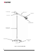
Counter Weight Balance Arm Lamp Head Swivel Joint Sterilizable Handle Extension Arm (Vertical Pole) Caster Base Bottom Counter Weight Figure 1: Celestial Star Mobile MRI 10 Sunnex Celestial Star MRI Service & Installation Manual
4.1.3 INSTALLATION IN THE MRI ROOM 1. Mount electrical box securely to a structural member outside of the safe perimeter (100 Gauss line/10mT) of MRI machinery with a fastener 1/2" diameter x 2" L. (Four holes are provided on the base plate of transformer box). 2. It is recommended not to mount the electrical box on wall. 3. Velcro is provided on the base plate of the electrical box and a rope and snap-on hook is provided on the electrical box to assist in proper installation. 4.
4.2 CELESTIAL STAR CEILING CS2050C-MRI Before you get started! Refer to Figure 4 for dimensions Dimensions and hole pattern of transformer bracket in the Appendix *It is recommended to install the transformer box outside the MRI room and run the power through an RF filter (Option 1). In the event the transformer box must the installed inside the MRI room (Option 2), the box must be secured to a structural member at a safe distance (100 Gauss line/10mT) away from the MRI machinery.
CAUTION! IF CONSTRUCTING ADDITIONAL SUPPORT STRUCTURES TO INSTALL THE LIGHT, THE LIMITATIONS AND REQUIREMENTS OF THE MRI ENVIRONMENT MUST BE CONSIDERED. NON-MAGNETIC MATERIALS SHOULD BE USED. CONSULT WITH YOUR MRI FACILITY MANAGER IF UNCERTAIN. 4.2.1 INSTALLATION OF THE EXTENSION ARM TO THE CEILING For illustrations please refer to Figure 4 and 5. Attach the extension arm to the ceiling prior to connecting the balance arm to the extension arm.
4.2.2 MOUNTING WITH AN ANGLE L-BRACKET AS SUPPORT CAUTION: WHEN MOUNTING CELESTIAL STAR CEILING MRI LIGHT, CARE MUST BE TAKEN TO USE ONLY NON-MAGNETIC MOUNTING STRUCTURE AND HARDWARE. An angle L-bracket can be used to secure the mounting bracket to a vertical plane above the drop (false) ceiling. Please refer to the dimensions below to determine the appropriate distance to the drop ceiling based on the desired clearance under the lowest point of the extension arm.
A: Floor to Drop Ceiling Distance 7’6” (2,25m) 8’ ( 2,4m) B: Clearance between BOTTOM of transformer bracket to drop ceiling C: Distance you get from bottom of extension arm to floor (Recommended: 6’3” – The user can specify need) 6.5” (165mm) 6.5” (165mm) 5’9” (1,75m) 6’3” (1,9m) 8’6” (2,55m) 6.5” (165mm) 6’9” (2,05m) 9’ (2,7m) 6.5” (165mm) 7’3” (2,2m) Table 1. Guideline for Celestial Star ceiling MRI mount Fixed ceiling Wiring Clearance (0.
Recommendations for mounting Celestial Star MRI ceiling (for hard ceiling to drop ceiling distance greater than 5 feet) When using a set up shown in figure 6: If the drop ceiling to hard ceiling distance is 3 feet or less than 3 feet, then one horizontal plate is recommended. If this distance is more than 5 feet then use of another horizontal plate above the first horizontal plate is recommended for assuring stability of the structure and stability of the light.
4cmX4cmX1cm , thk Angle 50 deg to 70 deg, to be determined at site (1 cm, thk) Side plates for support This side of L-bracket to be mounted square, otherwise the light may sway Figure 6: Celestial Star ceiling MRI mounting with horizontal plate and L-bracket (Recommendations) Figure 7: Celestial Star MRI L-bracket (Recommendations) NOTES 1. These are recommendations only; Sunnex is not responsible for all the material required for mounting.
4.2.3 ATTACH BALANCE ARM TO EXTENSION ARM Follow these instructions to attach balance arm to the extension arm 1. Do not attach the counter weight to the balance arm prior to connecting the balance arm to the extension arm. 2. Connect the male Molex connector with the female Molex connector and ensure that the positive latch on the connectors is achieved. Refer to Figure 3. Position the connection in such a way that the wires will not be compromised by securing the extension arm to the balance arm. 4.
Voltage output: Current: 14V DC 7.5 Amp. DC in secondary Sunnex does not recommend any specific filter but the specifications of the Celestial Star product must be carefully considered when selecting a filter. Some manufacturers that make RF filters are: Amphenol Canada, Spectrum Control, ERNI, Conec. (Amphenol Canada part# FCC17-A3W3AD-2X0 or equivalent filter should be used.) The voltage drop over the filter must be minimal to ensure proper performance of the light fixture.
RF Panel Hospital Grade Cord with Plug Output from Transformer Box to RF Filter Celestial Star MRI Ceiling Light Celestial Star MRI Power Supply RF Filter Celestial Star MRI Mobile Light MRI ROOM From RF filter to MRI Light Figure 9. Schematic for option 1 (Installing the transformer box outside MRI room using RF filter) Option 2 – Installing the transformer box inside the MRI room. The light is equipped with 30ft of cord on the secondary side and 10ft of cord on the primary side.
receptacle and the latch is fully engaged. (To disconnect, press lever on the receptacle and pull the lamp head connector.) Electrical box Lamp head connector Figure 10. Lamp lead connection with electrical box 6. Plug electrical box lead into a hospital grade electrical socket. 7. Lamp is ready for use. CAUTION! THE ELECTRICAL BOX CONTAINS FERROUS MATERIALS AND MUST BE HANDLED WITH CAUTION.
1. The light is supplied with a hard service cord (STOW 18/3, 600V, -35 OC to 105OC, 10 Amp per conductor @ 25 OC, approved as water resistant, oil resistant, outdoor use) suitable for ceiling hardwiring applications. This cord has 3 conductors (Hot, neutral and ground). The earth and neutral conductors are labeled as follows: EARTH NEUTRAL N This STOW cord runs through a hole in the transformer box. The outer diameter of the STOW cord is 0.378” (9.66mm). The hole in transformer box is 0.90” (22.
4.3 CELESTIAL STAR DUAL CEILING CS2050D-MRI Before you get started! *Drawing of dual mounting bracket provided in the Appendix *The dual mounted Celestial Star comprises two identical single ceiling mounted lights. The two lights are to be mounted back to back by creating structures described in the single arm installation procedures above.
5. OPERATING INSTRUCTIONS Power-on your light via the rocker switch in the back cover of the lamp head. The Celestial Star MRI is powered by a 200W isolation, step-down transformer that contains an internal thermal cut-off for your added safety. 6. ABOUT YOUR CELESTIAL STAR 6.
MOVING THE CELESTIAL STAR MOBILE When moving the light, please fold the balance arm toward the center of the light to prevent tipping.
6.2 CELESTIAL STAR MRI CEILING CS2050-C-MRI Figure 12: Celestial Star Ceiling dimensions REACH: With the lamp head/balance arm fully extended in the horizontal plane, the reach from the center of the ceiling “S” extension arm to beam center is, 58” (1.5m). If the light is mounted above the center of a 6’6" (2m) exam/treatment table, the beam center will reach 19” (0.5m) beyond its head and foot ends. A 10’ (3m) circle of coverage is available. Refer to figure 12.
CAUTION! DO NOT FORCE MOVEMENT PAST EITHER STOP POSITION, AS THIS WILL CAUSE DAMAGE TO THE ARM END JOINT. LAMP HEAD/YOKE MOVEMENT: The lamp head rotates over 350 degrees at its connection to the yoke. Movement is controlled by grasping either of the in-frame handles, or, with the aid of an added accessory, a sterilizable handle and mount assembly which may be fixed to the center of the lamp head. CAUTION ! DO NOT FORCE MOVEMENT PAST ITS STOP POSITION.
7. SERVICE AND MAINTENANCE ALWAYS bring the light outside the MRI room when performing any service on the light. This includes any cleaning and/or bulb replacements. The ceiling light balance arm can be detached and brought out of the MRI room for maintenance or repair. Assemble the mobile light outside of the MRI room. The safety guidelines of your MRI facility must NEVER be compromised. If in doubt, consult with your facilities manager on proper procedures.
7.2 HANDLE STERILIZATION The Delrin handles may be sterilized as you would any of your stainless steel instruments. However, it is of sufficient diameter to engage a disposable sleeve. The Delrin handle is an accessory for use with the Celestial Star (CS2050C/M-MRI) Specialty light. It is recommended that it is treated as a stainless steel item when submitting it to sterilization process. Two options are recommended: 1. A flash cycle at 275 – 279O F (135 – 137O C), for 16 minutes 2.
iv. v. vi. vii. viii. ix. x. xi. xii. counter clockwise. Grasp the bulb with one hand and unplug socket connector with the other. The notched ring assembly may now be removed from the lamp head and placed face down on a flat surface.
7.4 PREVENTIVE INSPECTION AND MAINTENANCE Lens in lamp head to be inspected once a month for cleanliness. 7.5 DISPOSAL OF PARTS While disposing parts of the product or the product itself, intender should consider local, state, country and international regulations about disposal of parts. Bulbs/fuses: Bulbs and fuses go in normal waste. All glass parts go in normal waste. Plastic parts: Plastic parts are to be put in recycling bins.
8. MARKINGS 8.1 SYMBOLS The functional earth conductor is not intended for use as a protective earth (chassis) ground.
9.
10. TROUBLESHOOTING Please refer to the following table for troubleshooting. CAUTION! DISCONNECT THE LIGHT FROM THE POWER SUPPLY BEFORE ATTEMPTING ANY OF THE ELECTRICAL CHECKS MENTIONED BELOW.
11. APPENDIX Guidance and Manufacturer’s Declaration — Emissions All Equipment and systems The Celestial Star MRI Light (CS2050M-MRI, CS2050C-MRI, CS2050ME-MRI, and CS2050CE-MRI) is intended for use in the electromagnetic environment specified below. The customer or user of the Celestial Star MRI Light (CS2050M-MRI, CS2050C-MRI, CS2050ME-MRI, and CS2050CE-MRI) should assure that it is used in such an environment.
Guidance and Manufacturer’s Declaration—Immunity All Equipment and Systems The Celestial Star MRI Light (CS2050M-MRI, CS2050C-MRI, CS2050ME-MRI, and CS2050CE-MRI) is intended for use in the electromagnetic environment specified below. The customer or user of the Celestial Star MRI Light (CS2050M-MRI, CS2050C-MRI, CS2050ME-MRI, and CS2050CE-MRI) should assure that it is used in such an environment.
Guidance and Manufacturer’s Declaration — Emissions Equipment and Systems that are NOT Life-Supporting The Celestial Star MRI Light (CS2050M-MRI, CS2050C-MRI, CS2050MEMRI, and CS2050CE-MRI) is intended for use in the electromagnetic environment specified below. The customer or user of the Celestial Star MRI Light (CS2050M-MRI, CS2050C-MRI, CS2050ME-MRI, and CS2050CE-MRI) should ensure that it is used in such an environment.
Recommended Separation Distances Between Portable and Mobile RF Communications Equipment and the Celestial Star MRI Light (CS2050M-MRI, CS2050C-MRI, CS2050ME-MRI, and CS2050CE-MRI) Equipment and Systems that are NOT LifeSupporting The Celestial Star MRI Light (CS2050M-MRI, CS2050C-MRI, CS2050ME-MRI, and CS2050CE-MRI) is intended for use in the electromagnetic environment in which radiated disturbances are controlled.
Celestial Star MRI Ceiling Transformer Box Mounting Bracket Sunnex Celestial Star MRI Service & Installation Manual 39
REV. 1.