7150 Minotaur Magnetic Commercial Indoor Cycling Bike Owner’s Manual Made in Taiwan
INDEX IMPORTANT SAFETY INFORMATION ..................................................................... 1 EXPLODED DRAWING ............................................................................................. 2 PARTS LIST................................................................................................................ 3 ASSEMBLY INSTRUCTION....................................................................................4-9 USER INSTRUCTION .........................................
IMPORTANT SAFETY INFORMATION We thank you for choosing our product. To ensure your safety and health, please use this equipment correctly. It is important to read this entire manual before assembling and using the equipment. Safe and effective use can only be achieved if the equipment is assembled, maintained and used properly. It is your responsibility to ensure that all users of the equipment are informed of all warnings and precautions. 1.
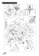
Exploded Drawing
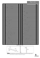
Parts list REF.
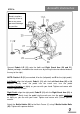
Assembly Instruction STEP 1: Attach the Front Stabilizer (18) and the Rear Stabilizer (14) to the Main Frame (Y) using 4 Bolts (10), 4 Washers (9) and 4 Nuts (8). Tighten and secure using spanner wrench.
Assembly Instruction STEP 2: Loosen adjustment L-Shaped Knob 1 (6) on main frame handlebar tube to remove insert protect cap, then insert the Handlebar Post (22) into the handlebar tube of the Main Frame (Y). Move Handlebar Post (22) to the desired height. Tighten the L-Shaped Knob 1 (6) to secure the Handlebar Post (22) into position. Slide the Handlebar (23) onto the Handlebar Post (22). Tighten the L-Shaped Knob 2 (17) to secure the Handlebar (23) into position.
Assembly Instruction STEP 3: Insert the Seat Post (42) into the seat tube located on the Main Frame (Y). Insert the Seat Slider (43) into the Seat Post (42). Tighten the Release Lever (6) to secure the Seat Slider (43) in place. Secure the Seat (1) onto the post of the Seat Slider (43). Tighten the seat clamp screw to secure the Seat (1) in place. Use L-Shaped Knob 1 (6) to adjust height of the seat, use L-Shaped Knob 1 (6) to adjust the seat back and forth.
STEP 4: Assembly Instruction IMPORTANT: Read instructions carefully, failure to do so may cause permanent damage to your bike. Connect Pedals L/R (11) onto the Left and Right Crank Arm (20 and 21). (Before you begin, immobilize the crank arms by turning the tension control knob all the way to the right). NOTE: Pedals L/R (11) are marked, L for the (left pedal) and R for the (right pedal). Left Pedal: align the left pedal, Pedal L (11) with the Left Crank Arm (20) at 90 degrees.
Assembly is complete!
Before beginning use of equipment, please be sure to inspect the entire bike carefully. Ensure that all moving and stationary parts have been properly installed and are operational. Inspect all screws, nuts and bolts as well to make sure that they are tightened and secure. MOVING There are Moving Wheels (39) on the front stabilizer. Hold the handlebar, and tilt the bike towards you until the wheels touch the ground. Then you can move the bike.
User Instruction ASSEMBLY Properly assembling the equipment before use is very important. Be sure to follow all instructions as detailed in the assembly instructions section of the owner’s manual. ADJUSTING THE RESISTANCE Adjust the resistance of the bike using the Tension Knob. Increase the level of resistance by turning the tension knob to the RIGHT, and decrease the level of resistance by turning the tension knob to the LEFT.
Maintenance IMPORTANT: Safe and effective use can only be achieved if the equipment is assembled, maintained and used properly. It is your responsibility to ensure that the equipment is maintained regularly. Any components found to be worn and/or damaged should be replaced before continuing use of the equipment. Equipment should only be used and stored indoors.