ASUNA 9700 Elevated Performance Treadmill Workstation
INDEX IMPORTANT SAFETY INSTRUCTIONS............................................................. 1 - 2 ELECTRICAL GROUNDING INSRUCTIONS..................................................... 2 CAUTION: BEFORE AND AFTER RUNNING ON THE TREADMILL............... 3 RUNNING DECK LUBRICATION........................................................................ 3 - 4 EXPLODED DIAGRAM............................................................................................ 5 PARTS LIST...........................
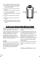
IMPORTANT SAFETY INSTRUCTIONS Please read the following basic precautions prior to use of the treadmill: * Never operate the treadmill with the air openings blocked. * Keep air openings free of lint, hair and alike items. * Please retain this manual for future reference. WARNING 1. This treadmill requires a dedicated circuit as 110 V / 220 V, 15 / 10 AMP separately that is not shared by any other electrical appliances. Failure to do so can damage the electronics and the motor and will void the warranty. 2.
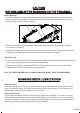
FRONT 2 FEET MIN. LEFT SIDE 2 FEET MIN. TOP VIEW RIGHT SIDE REAR 2 FEET MIN. 18. Do not walk or jog barefoot or without shoes. 19. Do not walk or jog in loose shoes or slippers. Athletic shoes are always recommended while using this treadmill. 20. Never walk or jog while wearing loose fitting clothing. 21. When walking or jogging always stay on the forward part of the treadmill. 22. Never jog or walk faster than it is comfortable for you. 23. Do not jump on the treadmill or from side to side. 24.
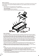
CAUTION BEFORE AND AFTER RUNNING ON THE TREADMILL Before Running: 1. Read the manual first to be familiar with the digital display and other important features. 2. Before starting the treadmill, always stand on the two side rails on both sides (not on the running belt) as shown in the drawing. 3. Press in Safety Key underneath the display and have the safety clip securely attached to an article of clothing. 4. Start the treadmill and allow it to reach a speed of at least 0.
What to lubricate? Do not lubricate with anything other than our approved lubricant. Your treadmill comes with one 30 ml tube of silicone. You may order additional lubrication from your distributor, which comes in 200 ml silicone bottle: • 200 ml silicone in one bottle with 13.
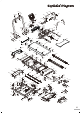
Exploded Diagram 132 120 132 132 98 120 132 12 135 12 12 12 5 113 5 117 99 129 12 5 5 12 125 129 122 12 127 122 104 103 102 105 128 130 41 100 41 12 5 5 41 81 101 49 83 85 82 135 111 108 41 107 100 135 135 106 41 82 135 86 81 128 101 24 110 130 84 84 92 109 55 55 131 116 67 67 67 12 41 41 131 36 12 131 131 127 12 131 41 41 5 12 12 5 41 12 131 12 129 129 114 129 126 67 12 129 12 115 41 41 41 41 12 12 118 12 5 5 129 12 123 135 118 124 129 1
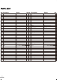
Parts List No. Description Specs. Qty No. Description Specs. Qty 1 Fastener OSBR-26 2 38 Bush Ø15.8 x 2.7t x 72.5L 2 2 Fixing Cap Ø12 x Ø3.5 PVC 1 39 Washer Ø10 x Ø21 x 2.0t 4 3 Round Cushion 60D 6 40 Fastener OSBR - 22 1 4 Screw M3 x 10L 4 41 TP Screw 5/32" x 12.7L 30 5 Nylon Nut M8 21 42 Bolt M10 X 100L 2 6 Cable 3-line x 1300mm 1 43 Wheel Ø50 - TPU 2 7 Sensor 1100mm 1 44 Shaft Ø19.4 x4L + Ø14 x 79L 2 8 Main Frame #337 1 45 Bush Ø8.
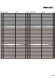
Parts List No. Description Specs. Qty No. Description Specs. Qty 72 Nylon Nut M10 - P1.5 1 104 Cable 600mm / 7P 1 73 Incline Motor JS-19 1 105 Armrest Frame #337 1 74 Rear Roller Ø42 x 560L 1 106 Safty Key Box #337 - ABS 1 75 PVC Trim 1100mm - PVC 2 107 Safty Key #337 - ABS 1 76 Runnong Belt 500 x 2710 x 1.6t 1 108 Safty Key Clip T-A1-28 / PH-60 1 77 Belt 210J6V 1 109 Screw M2.
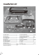
Assembly Parts List A1 A5 A2 A7 A6 A3 A4 AJ AI AH A8 AB AA AC AD A1. Main Frame .................................. A2. Front Post .................................... A3. Computer Set .............................. A4. Storage Box ................................. A5. Desk Set ...................................... A6. Right Handlebar ........................... A7. Left Handlebar ............................. A8. Back Cover .................................. AA. Bolt Set (M8x50L) .............
Assembly Instructions Step 1: A2 A1 First, please note the end with wire on the Front Post (No. A2) is for the right side of Main Frame (No. A1). Then ask one person to hold Front Post (No. A2) and connect the wire from Main Frame (No. A1) and Front Post (No. A2). Tuck the connector into the hole on the Main Frame (No. A1). Step 2: A2 AB A1 Use Bolt Sets (AA & AB) to attach Front Post (No. A2) onto the Main Frame (No. A1). Please be careful not to damage the wire and connector.
Step 5: Use Bolt Set (AG) to attach. AG Step 6: Use Screw (AF) to attach the Back Cover (No. A8) on the Storage Box (No. A4). A8 8 AF Step 7: Use Plate (AI) and 4 Screws (AH) to attach Storage Box (No. A4) to the Desk Set (No. A5) from underneath. A4 4 AH AI A5 5 AH 10 Step 8: Use Screw (AH)(shorter one) to also attach Storage Box (No. A4) to the Desk Set (No. A5) from the hole as shown underneath central. Connect another wire from Computer Set (No. A3) and Desk Set (No. A5) .
Step 9: This photo shows the final assembly of Computer Set (No. A3), Storage Box (No. A4) & Desk Set (No. A5). Step 10: A5 5 A2 2 Ask one person to hold the above final assembly of Desk Set (No. A5) on the top end of Front Post (No. A2). Then, connect the wire from Desk Set (No. A5) and Front Post (No. A2). Tuck the connector into the hole on Front Post (No. A2). Step 11: Use Bolt Set (AC) to attach Desk Set (No. A5) on the Front Post (No. A2). Please be careful not to damage the wire and connector.
Step 13: Then use Bolt Set (AE) to attach Right Handlebar (No. A6) on the frame of Desk Set (No. A5). Do not tighten the bolts yet. A6 6 A5 5 AD A5 5 A6 6 Step 14: Use Bolt & Spacer (AD) to attach Right Handlebar (No. A6) on the right side of Desk Set (No. A5). Follow the same procedure to attach Left Handlebar (No. A7) on the left side of Desk Set (No. A5). Then, tighten the bolts on Step 13. Step 15: Plug in Power Cable (AK) on the Main Switch located on the right side of Main frame (No. A1).
Treadmill Operation Speed / Incline Range: Running Mode: 0.5 ~ 7.5 mph, Level 0 ~ 15 Climbing Mode: 0.5 ~ 3.7 mph, Level 15 ~ 40 Program: Running Mode: (1) 12 preset with Difficult Level 1 ~ 3 (2) 3 targets (Time, Distance, Calories) (3) HRR (E, M, T, A, I) (0.5 ~ 6.2 mph, Level 0~ 15) (4) Fat Climbing Mode: (1) 5 preset (2) 3 targets (Time, Distance, Calories) (3) HRR (E, M, T, A, I) (0.5 ~ 2.
INCLINE window: (A) Level 0 ~ 15 for Running mode, Level 15 ~ 40 for Climbing Mode (B) Age 10 ~ 99 years old. Defaulted setting: 30 years old. (C) Difficult Level 1 ~ 3 TIME window: 00:00 ~ 99:59 SPEED window: (A) Running Mode 0.5 ~ 7.5 mph, Climbing Mode 0.5 ~ 3.7 mph (B) Weight 44 ~ 309 lbs Speed unit: KM or Mile (Defaulted setting Mile) Dot Matrix:16 x 29 Dot Function Keys: Climb Mode: Quick incline selection for Climbing mode.
FOR PROGRAM OPERATION: Step 1: Press Incline / to choose U0, U1, U2 or U3. Step 2: Press Enter & Speed / to key in gender, age, height, weight and resting heart rate (RHR). Step 3: Press Enter to confirm Step 4: Press Start to begin or press Incline / or Speed / to choose either Preset, Target or HRR program for operation. Preset Program Operation: Step 1: Press Incline / or Speed / to choose P1 ~ P12 for Running (P1 ~ P5 for Climbing).
Note: 1. For HRR program operation, the user needs to wear a transmitter or hold both hands on the hand pulse sensors. This is found on the handlebars to detect heartbeat. 2. If user's heart rate is lower than set target per detection, the speed will automatically increase 0.2 mile. When the speed is at 6.2 mph, but user's heart rate is still lower, then incline will increase 1 level each time. When the speed is at 6.
FAT Program Step 1: Press Incline / or Speed / to choose FAT program. Step 2: Press Enter and then Start to start detecting. After about 12 seconds, the computer will show the user's BMI, BMR, FAT% and BODY TYPE. Since this treadmill is not for medical use, the above data is only reference. Please note user has to hold both hands on the hand pulse sensors. LCD will show NO PULSE if the computer could not detect user's heartbeat.
BODY TYPE: 1~5 1 2 3 4 5 Petite Underweight Normal Overweight Extremely Overweight FAT % Male 10 ~ 20 % 20 ~ 25 % Over 25 % Normal Overweight Extremely Overweight Female 15 ~ 25 % 25 ~ 35 % Over 35 % Normal Overweight Extremely Overweight COOL DOWN MODE: 1. After pressing Cool Down , incline will be lowered down to the lowest level, and speed will lower down to 1.2 mph. 2. Time, Calories, and Distance will keep accumulating. 3. Pressing Cool Down again will resume to the original STEP COUNT: 1.
Running Mode Preset Program Profile and Data P1 ~ P4 PROGRAM PROFILE P1 P2 P3 P4 19
P1 ~ P4 PROGRAM DATA SPEED P1 LEVEL 1 SPEED INCLINE SPEED INCLINE SPEED INCLINE SPEED INCLINE Interval 1 2.0 MPH 0% 2.0 MPH 0% 3.0 MPH 0% 3.0 MPH 0% Interval 2 3.0 MPH 0% 4.0 MPH 0% 3.0 MPH 0% 4.0 MPH 0% Interval 3 3.0 MPH 0% 6.0 MPH 0% 6.0 MPH 0% 5.0 MPH 0% Interval 4 4.0 MPH 0% 2.0 MPH 0% 6.0 MPH 0% 6.0 MPH 0% Interval 5 4.0 MPH 0% 4.0 MPH 0% 6.0 MPH 0% 7.0 MPH 0% Interval 6 5.0 MPH 0% 6.0 MPH 0% 7.5 MPH 0% 7.5 MPH 0% Interval 7 5.0 MPH 0% 2.
P 5 ~ P 8 PROGRAM PROFILE P5 P6 P7 P8 21
P5 ~ P 8 PROGRAM DATA SPEED P5 P6 P7 P8 LEVEL 1 SPEED INCLINE SPEED INCLINE SPEED INCLINE SPEED INCLINE Interval 1 4.0 MPH 2% 4.0 MPH 2% 4.0 MPH 2% 4.0 MPH 3% Interval 2 4.0 MPH 4% 4.0 MPH 3% 4.0 MPH 4% 4.0 MPH 6% Interval 3 4.0 MPH 4% 4.0 MPH 4% 4.0 MPH 6% 4.0 MPH 6% Interval 4 4.0 MPH 6% 4.0 MPH 5% 4.0 MPH 2% 4.0 MPH 8% Interval 5 4.0 MPH 6% 4.0 MPH 2% 4.0 MPH 4% 4.0 MPH 8% Interval 6 4.0 MPH 4% 4.0 MPH 3% 4.0 MPH 6% 4.0 MPH 3% Interval 7 4.
P 5 ~ P 8 PROGRAM PROFILE P9 P10 P11 P12 23
P9 ~ P12 PROGRAM DATA SPEED P9 P10 P 11 LEVEL 1 SPEED INCLINE SPEED INCLINE SPEED INCLINE SPEED INCLINE Interval 1 2.0 MPH 2% 2.0 MPH 2% 3.0 MPH 2% 3.0 MPH 3% Interval 2 3.0 MPH 4% 4.0 MPH 3% 3.0 MPH 4% 4.0 MPH 6% Interval 3 3.0 MPH 4% 6.0 MPH 4% 6.0 MPH 6% 5.0 MPH 6% Interval 4 4.0 MPH 6% 2.0 MPH 5% 6.0 MPH 2% 6.0 MPH 8% Interval 5 4.0 MPH 6% 4.0 MPH 2% 6.0 MPH 4% 7.0 MPH 8% Interval 6 5.0 MPH 4% 6.0 MPH 3% 7.5 MPH 6% 7.5 MPH 3% Interval 7 5.
Climbing Mode Preset Program Profile and Data P1 ~ P5 PROGRAM PROFILE P1 P2 P2 P3 P4 P5 25
P 1 ~ P 5 PROGRAM DATA SPEED LEVEL 1 Interval 1 Interval 2 Interval 3 Interval 4 Interval 5 Interval 6 Interval 7 Interval 8 Interval 9 Interval 10 Interval 11 Interval 12 Interval 13 Interval 14 Interval 15 Interval 16 Interval 17 Interval 18 Interval 19 Interval 20 Interval 21 Interval 22 Interval 23 Interval 24 Interval 25 Interval 26 Interval 27 Interval 28 Interval 29 26 P1 SPEED INCLINE 3.0 MPH Level 8 3.0 MPH 10 3.0 MPH 11 3.0 MPH 15 3.0 MPH 18 3.0 MPH 20 3.0 MPH 22 3.0 MPH 23 3.0 MPH 25 3.
Error Code & Trouble Shooting E1 (Error 1): When the machine starts and the computer does not detect signal from the sensor for 7 seconds, E1 will be shown on the computer. E6 (Error 6): When the machine starts and the computer could not read the VR signal from incline motor for 6 seconds, E6 will be shown on the digital display. If any above trouble happens, please consult the distributor. E3 (Error 3): E3 shows when the cable from computer and control box is not well-connected or damaged.
Aligning the Running Belt Ensure the running belt is centered on your treadmill at all times. FIGURE A Running style and Non-level surface may cause the belt to drift off center. Minor adjustments to the two bolts at the rear of the treadmill are necessary when the belt has drifted off center. See fig. A & B. 1 . Press the Master Power Switch (located at the front of the treadmill) to the ON position and ensure Safety Key is properly placed onto DRIFTS TO THE RIGHT the computer console.
Cleaning Make sure the treadmill is off and unplugged from the electrical outlet . To remove dust, use a small vacuum nozzle to carefully vacuum around all visible components . To remove film or dust, use a slightly damp rag with a mild cleaning agent. Spray this onto the rag only. Becareful not to immerse any treadmill component in any liquids . Inspecting Fasteners & Wiring Check that all fasteners are properly tightened, and all wiring is securely in place .
When and How to Maintain Your Motorized Treadmill ITEM DAILY (Before Use) Machine Itself Examine if the frame is stable for exercise. Adjust balancer to make it stable and positioned on the ground. Use dry cloth to wipe and clear sweat and dust on the surface of machine. Location Assure enough safe space around the machine, and make sure no dangerous objects are around. Use wet cloth to clean the ground. Do not put wax on the ground.