44 LBS FLYWHEEL BELT DRIVE COMMERCIAL INDOOR CYCLING BIKE SF-B1735 USER MANUAL IMPORTANT! Please retain owner’s manual for maintenance and adjustment instructions. Your satisfaction is very important to us, PLEASE DO NOT RETURN UNTIL YOU HAVE CONTACTED US: support@sunnyhealthfitness.com or 1- 877 - 90SUNNY (877-907-8669).
IMPORTANT SAFETY INFORMATION We thank you for choosing our product. To ensure your safety and health, please use this equipment correctly. It is important to read this entire manual before assembling and using the equipment. Safe and effective use can only be achieved if the equipment is assembled, maintained, and used properly. It is your responsibility to ensure that all users of the equipment are informed of all warnings and precautions. 1.
EXPLODED DRAWING 1 39 36 89 3 33 33b 34 31 35 33a 40 37 39 37 40 36 1 4 5 6 2 7 8 38 9 21 2 12 10 14 13 13 18 17 8 12 17 18 24 32L 87L 27L 22 8 15 19 11 20 23 2 3 11 16 13 14 13 15 19 20 10 29 26 18 17 18 32R 28 27R 87R 17 18 19 26 18 19 20 25 #A S13-14-15 26 18 20 26 18 30 2 #B S6 #C S10-13-17-19 1PC
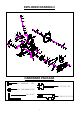
EXPLODED DRAWING 2 84 41 42 43 44 53 52 54 55 56 53 57 32L 57 60 62 63 77 45 46 47 51 50 74 81 75 49 48 37 53 59 65 59 59 59 82 76 78 37 83 79 88 80 64 77 79 37 58 21 79 78 59 61 67 59 76 75 74 59 59 85 68 28 64 66 70 63 59 69 70 72 70 61 85 70 86 71 32R 73 HARDWARE PACKAGE #17 M10*25*S6 4PCS #A S13-14-15 1PC #18 d10*Φ20*2.
PARTS LIST No.
No. Description Spec. Qty. No. Descriptio Spec. Qty. 1 79 Bearing 6202-2RS 3 1 80 Inertia Axle Φ15*156.5*M12*1*3 4.5*34.5 1 1 81 Inertia Wheel 22*Φ460*75*28*Φ6 0*34*PL 1 82 Wave Washer D16*Φ21*0.3 1 Spacer Φ20*Φ15.1*14.5 1 65 Stainless Steel Board 66 Wave Washer 67 Inner Belt Cover 68 Belt Wheel Φ200*20*Φ54*4-M 8*3PL 1 69 Middle Axle Φ25*185*64.8*64.
ASSEMBLY INSTRUCTIONS We value your experience using Sunny Health and Fitness products. For assistance with parts or troubleshooting, please contact us at support@sunnyhealthfitness.com or 1-877-90SUNNY (877907-8669). STEP 1: Unscrew the 4 Screws (No. 26) with Allen Wrench (No. B) and remove the 4 Flat Washers (No. 18), Shipping Front Tube (No. 25), and Shipping Rear Tube (No. 30). #B S6 1PC 26 18 26 18 25 You may save these parts [Screws (No. 26), Flat Washers (No. 18), Shipping Front Tube (No.
We value your experience using Sunny Health and Fitness products. For assistance with parts or troubleshooting, please contact us at support@sunnyhealthfitness.com or 1-877-90SUNNY (877907-8669). S14 #23 M5*16*Φ8.5 2PCS #A S13-14-15 1PC #11 d5*Φ13*1 2PCS #87L/R 9/16*H8*S19-L/R 2PCS S19 STEP 3: WARNING! Read instructions carefully as improper assembly may cause permanent damage to your bike. #C S10-13-17-19 1PC 87R 23 23 22 11 27L 32L 87L 28 32R 27R Remove the 2 Nylon Nuts (No.
We value your experience using Sunny Health and Fitness products. For assistance with parts or troubleshooting, please contact us at support@sunnyhealthfitness.com or 1-877-90SUNNY (877907-8669). STEP 5: Loosen and pull out the [handlebar] T Shape Knob 2 (No. 10). Insert the Handlebar (No. 1) into the tube located on the front of the Main Frame (No. 28). Adjust the Handlebar (No. 1) to the desired height, then secure it in place by reinserting and tightening the T Shape Knob 2 (No. 10).
ADJUSTMENTS AND USAGE GUIDE ADJUSTING THE HEIGHT AND BALANCE #A S13-14-15 In order to achieve a smooth and comfortable ride, you must ensure 12 of the bike is secured. If you notice that the bike is that the stability unbalanced during use, you should adjust the Foot Levelers (No. 20) located beneath the Front and Rear Stabilizers (No. 16 & No. 29) of the bike. To do so, use Spanner (No. A) to loosen Nut (No. 19) by turning it clockwise (direction A). With the nut loosened, rotate the Foot Leveler (No.
PEDAL STRAP ADJUSTMENT Your feet should be secured in the toe clips during exercise. Place your feet as far forward into the toe-clips as you can. With your feet in place, turn the crank to bring one foot within arm’s reach then grasp the pedal strap and pull it upward to tighten the toe-clip cage. Insert the strap back into the hoop of the toe-clip. Repeat this process to secure your other foot. ADJUSTING THE RESISTANCE Adjust the resistance of the bike using the Tension Control Knob (No. 84).
REMOVE THE CRANK ARM 32L 61 61 32R #B S6 #B S6 61 61 A B C D TO REMOVE THE CRANK ARM Unscrew 2 Screws (No. 61) counter-clockwise with the Allen Wrench (No. B). Remove the 2 Screws (No. 61) and pull out the Left & Right Crank Arm (No. 32L & 32R). NOTE: The hexagonal hole on the middle axle and the crank arm should be aligned when assembling. TO REASSEMBLE THE CRANK ARM Attach the Left & Right Crank Arm (No. 32L & 32R) to the middle axle. Attach the 2 Screws (No.
EXERCISE METER FUNCTION BUTTONS MODE Press to select the function displayed or enter value after setting. Press and hold for 2 seconds to enter the RACE interface in STOP mode. SET To set up the target value of TARGET, TIME, DIST, CAL. Press the button and hold for 2 seconds to speed up the increment during stop mode. RESET Press the button to reset function value during setting mode. Press the button and hold for 2 seconds to reset all value except Odometer to zero.
RACE MODE Press and hold MODE for 2 seconds to enter RACE mode. 1. TARGET: the preset CADENCE. 2. In STOP mode, press SET key to enter the TARGET setting in stop mode Press SET to increase the CADENCE five at a time. The setting change is 15………110→115→120→15→ ↑←←←←←←←←←←←↓ 3. The setting range of 15 -120 (Preset value is 60 CADENCES. It equals six bars) 4. Each bar equals 10 CADENCE. Total is 12 bars.
MAINTENANCE INSTRUCTIONS This is general information for daily, weekly and monthly maintenance to be performed on your bike. DAILY MAINTENANCE After each exercise session, wipe down all the equipment: seat, frame, handlebars. Pay special attention to the seat post, handlebar post and belt guard. Sweat is very corrosive and may cause problems that result in parts replacement later. 1. Get on the bike and engage the drive train. 2. Pay attention to any vibrations felt through the pedals.