MAGNETIC INDOOR CYCLING BIKE SF-B1805 USER MANUAL IMPORTANT! Please retain owner’s manual for maintenance and adjustment instructions. Your satisfaction is very important to us, PLEASE DO NOT RETURN UNTIL YOU HAVE CONTACTED US: support@sunnyhealthfitness.com or 1-877-90SUNNY (877-907-8669).
IMPORTANT SAFETY INFORMATION We thank you for choosing our product. To ensure your safety and health, please use this equipment correctly. It is important to read this entire manual before assembling and using the equipment. Safe and effective use can only be achieved if the equipment is assembled, maintained and used properly. It is your responsibility to ensure that all users of the equipment are informed of all warnings and precautions. 1.
EXPLODED DIAGRAM 3
HARDWARE PACKAGE #16 1PC #27 1PC #32 Φ40XΦ10X4 1PC #42 S10,13,14,15,17 1PC #43 S13,15 1PC 4
PARTS LIST No. 1 Main Frame 1 23 2 Front Stabilizer 1 24 3 Front End Cap 2 25 Description Hex Stopper Screw Hex Socket Cap Screw Handlebar Post 4 Rear End Cap 2 26 Handlebar 1 5 Foot Pad 2 27 L Shaped Knob 1 6 Carriage Bolt M8XL100 4 28 Seat 1 7 Flat Washer 6 29L/R Crank 1 pr. 8 Spring Washer Φ8XΦ16X1.
ASSEMBLY INSTRUCTIONS STEP 1: Remove the preassembled 4 Carriage Bolts (No. 6), 4 Flat Washers (No. 7), 4 Spring Washers (No. 8) and 4 Acorn Nuts (No. 9) from Front & Rear Stabilizer (No. 2 & No. 12) with the Spanner (No. 42). Attach the Front & Rear Stabilizer (No. 2 & No. 12) to the Main Frame (No. 1) using 4 Carriage Bolts (No. 6), 4 Flat Washers (No. 7), 4 Spring Washers (No. 8) and 4 Acorn Nuts (No. 9) that were just removed. Tighten and secure with the Spanner (No. 42). Insert the Seat Post (No.
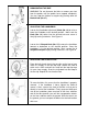
NOTE: ADJUSTING THE SEAT POST AND THE SEAT HORIZONTAL POST When the Seat Post (No. 28) is at the lowest setting, the handles on Knobs (No. 16) may not have enough space to turn (See drawing on left). If this happens, the handles can be adjusted. To adjust the handle, pull on the handle, turn the handle to a position that is not blocked, and release the handle. Repeat as needed. It may take several adjustments to get the handle to a position where it can be turned.
ADJUSTMENTS GUIDE ADJUSTING THE BALANCE In order to achieve a smooth and comfortable ride, you must ensure that the stability of the bike is secured. If you notice that the bike is unbalanced during use, you should adjust the foot levelers located beneath the front and rear stabilizers. To do so, use Spanner (No. 42) to loosen Hex Screw (No. 33) by turning it clockwise (direction A). With the screw loosened, rotate Foot Pad (No. 5) until it sits level with the surface that the bike is on.
DISMOUNTING THE BIKE WARNING! Do not dismount the bike or remove your feet from the pedals until the pedals have stopped completely. You can stop the flywheel at anytime by pushing down on Brake Knob (No. 31). ADJUSTING THE HANDLEBAR Loosen the [handlebar adjustment] Knob (No. 16) to raise or lower the handlebar to the desired position. Make sure the Knob (No. 16) settles into the desired hole and secure it firmly by turning clockwise. See Figure A. Loosen the L Shaped Knob (No.
MAINTENANCE INSTRUCTIONS This is general information for daily, weekly and monthly maintenance to be performed on your bike. DAILY MAINTENANCE MONTHLY MAINTENANCE After each exercise session, wipe down all the equipment: seat, frame, handlebars. Pay special attention to the seat post, handlebar post and belt/chain guard. Sweat is very corrosive and may cause problems that require parts replacement later. 1.