FLYWHEEL ELLIPTICAL TRAINER S F - E 2 310 OWNER’S MANUAL IMPORTANT! PLEASE READ THIS MANUAL CAREFULLY BEFORE USING THE BIKE. For Customer Service, please contact: support@sunnyhealthfitness.
Important Safety Information We thank you for choosing our product. To ensure your safety and health, please use this equipment correctly. Please read the information below carefully before using this equipment. 1. It is important to read this entire manual before assembling and using the equipment. Safe and effective use can only be achieved if the equipment is assembled, maintained and used properly. 2.
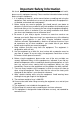
45 109 41 110 42 32 33 39 7 30 26 17 2 23 29 108 87 27 43 16 10 9 3 86 60 59 S8 107 15 16 83 61 9 10 1 97 S6 106 76 10 83 96 105 84 91 76 10 85 86 96 91 2 13 41 76 10 69 42 93 91 90 73 33 26 20 17 5 46 32 33 110 8 34 22 35 3332 28 93 93 94 95 94 29 74 39 42 93 39 93 76 10 68 75 70 70 72 32 33 38 89 93 104 67 93 93 11 14 12 81 87 82 79 91 16 15 9 10 12 13 21 9 91 92 44 92 88 16 15 17 101 101 11 14 78 72 77 72 72
PARTS LIST NO DESCRIPTION QTY NO DESCRIPTION QTY 1 Main frame 1 37 Left pedal 395*160*52 1 2 Front stabilizer 1 38 Right pedal 395*160*52 1 3 Rear stabilizer 1 39 Bolt M8*45*20*S14 grade A 4 4 Left handle bar 1 40 End cap J40*25*15 2 5 Right handle bar 1 41 End cap J60*30*15 2 2 42 Alloy wrap Φ28*4*φ24*12*Φ16.
73 Nut M12*1*H19.5*S19 2 92 Screw M5*20*Φ8.5 2 74 Washer d12*φ24*2.0 2 93 Screw ST4.8*16*Φ10 8 75 Adjusting screw M8*83*Φ12*5 2 94 Screw M5*12*Φ8.5 2 76 Screw M10*16*S6 4 95 Washer d5*Φ10*1 2 77 Sensor stopper 1 96 Washer φ6.
HARDWARE PACKAGE 5
ASSEMBLY INSTRUCTIONS STEP 1: 1 76 10 104 76 10 105 A. Unscrew the screws (76) with wrench (S6), then remove and discard the shipping rear tube (105) and the shipping front tube (104). B. You can save these parts for future packaging and transportation of the bike if desired.
STEP 2: 9 10 9 10 1 2 3 A. Secure front stabilizer (2) and rear stabilizer (3) to main frame (1) with screws (9) and washers (10).
STEP 3: S13-14-15 S14 S8-14-22 22 18 20 19 103 21 27 21 5 4 1 103 19 20 18 22 A. Attach swing rod axle (27) into main frame (1), insert wave washer (21) into the swing rod axle (27) on both sides; B. Secure left handle bar (4) and right handle bar (5) to swing rod axle (27) with bolts (18), spring washers (20), washers (19) and D shape washers (103); * NOTE: In order to tighten bolt #18 on both sides, use a spanner to hold on the left side, and to tighten the right side.
STEP 4: S22 S8 S8-14-22 4 23 20 28 26 5 6L 22 45 110 22 7 26 20 31 23 28 80 6R 22 31 43 22 79 8 44 110 46 A. Secure swing rod (6L) to left handle bar (4) and Swing rod (6R) to right handle bar (5) with bolts (23), arc washers (26), spring washers (20) and nuts (28); B. Secure right pedal post (8) to crank on the big chain wheel (79) with right pedal bolt (46), wave washer (110) and right nut (44) by screwing clockwise; C.
STEP 5: 39 37 7 32 33 39 38 8 32 33 A. Secure left pedal (37) to left pedal post (7) with bolts (39), washers (32) and nuts (33); B. Secure right pedal (38) to right pedal post (8) with bolts (39), washers (32) and nuts (33).
STEP 6: 97 78 100 102 100 98 1 A. Secure computer holder (102) to main frame (1) with screws (100); B. Secure computer (97) to computer holder (102) with screws (78), then connect the wire of computer (97) with trunk wire (98). Assembly is finished.
MAINTENANCE I 22 33 31 22 II 30 After a period of time, the grease in the joint will become dry and it might cause noise. Please follow instructions on how to lubricate the joint below: Remove end caps (22), bolt (31) and nut (33) as diagram Ⅰ, then remove spacer (30) as diagram Ⅱ, and add some grease on the surface and inside of spacer (30) to decrease the rub, after finishing it, please assembly spacer (30), bolt (31), nut (33) and end caps (22) back.