
Product Manual


RELAY KIT #43274020
For Models: SIR25-45
RELAY KIT #43274020
PART NO. DESCRIPTION
03139040
30200010
30399000
42706990
43276000
43277020
3/16” Slide Terminal
Ring Terminal
1/4" Terminal Adaptor
Wire Connection Diagram
Relay Sub-assembly
Form, Installation Instructions
INSTRUCTIONS:
WARNING: DISCONNECT THE ELECTRIC
POWER TO THE HEATER AND SHUT OFF THE
GAS SUPPLY TO THE MANIFOLD CONTROL
BEFORE MAKING THIS CHANGE.
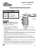
1. Loosen the screws of the transformer as
shown in the illustration. Slide the bracket of
the relay assembly under the transformer and
retighten the screws.
2. Disconnect the motor wire lead from L1 of the terminal block. Cut off the old 1/4" slide terminal and
replace it with the 3/16" slide terminal supplied in this kit. Reconnect this wire lead to the No. 4 terminal
on the relay.
3. Disconnect the wire lead of the red light from the terminal adaptor of the transformer. Cut off the old 1/4"
slide terminal and replace it with the ring terminal supplied in this kit. Connect this wire lead to the
ground screw (green coated screw) located above the terminal block.
4. Remove and discard the wire lead that is connected between the transformer and the air pressure
switch.
5. Place the terminal adaptor supplied in this kit on the free terminal of the air pressure switch.
6. Connect the black wire lead located at the No. 3 terminal of the relay to L1 of the terminal block.
7. Connect the red wire lead located at the No. 5 terminal of the relay coil to the new terminal adaptor on
the air pressure switch.
8. Connect the white wire lead located at the No. 1 terminal of the relay coil to the existing terminal adaptor
on the transformer.
9. Connect the new 24-volt thermostat (supplied as an accessory) with one lead connected to the terminal
adaptor on the air pressure switch and the other lead to the free terminal on the transformer.
10. Place the new adhesive-backed wiring diagram supplied in this kit over the existing wiring diagram.
NOTE: All field wiring connections are indicated by dotted lines on the Wiring Diagram provided in this kit.
Sep–04 A –1– Form #43277020
THIS KIT IS FOR THE FIELD INSTALLATION OF A 24-VOLT
THERMOSTAT FOR OPERATION OF A SINGLE HEATER.
RELAY
ASSEMBLY
TRANSFORMER
SCREWS