
Product Manual

–7– Form #43219030
June 09
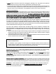
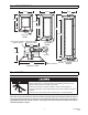
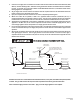
8) OPTIONAL PARABOLIC REFLECTOR EXTENSION ASSEMBLY
The heater is completely factory assembled and requires no field assembly. If the optional parabolic reflector
extension is utilized, locate and identify the end panels and side panels as shown in the following diagram.
Attach the side panels as shown. Attach the end panels so that the end flanges of the end panels overlap the side
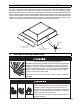
panels. Attach the side panels and end panels together with the screws provided in the kit. Attach the remaining
screws as shown in Detail A. This is to ensure that the Parabolic Reflector Extension is securely attached to the
reflector. The clearances to combustibles (shown on the clearance label that is secured to the reflector on the
control end of the heater and in Section 4 of these instructions) must be closely observed.
Sheet Metal
Screw
DETAIL A
(Section View)
Parabolic Reflector Extension
(END PANEL)
Parabolic Reflector Extension
(SIDE PANEL)
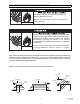
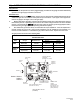
9) GAS CONNECTIONS AND REGULATION
An approved connector, suitable for the environment of equipment
usage, is required. Visible or excessive swaying, flexing and
vibration of the gas connections must be avoided to prevent
failure. Neither the gas pipe nor the connector shall be placed
in the flue discharge area. In no case shall the gas supply
support the weight of the heater.
Failure to do so may result in death, serious injury or property
damage.
FIRE AND EXPLOSION HAZARD
Tighten flexible gas hose and components securely.
Improperly connected gas lines may result in fire,
explosion, poisonous fumes, toxic gases, asphyxiation
or death. Connect gas lines in accordance to national,
state, provincial and local codes.
Failure to do so may result in death, serious injury or
property damage.
FIRE AND EXPLOSION HAZARD