
TapeMat Installation Manual


7 of 32
Do not remove this nameplate label. The
electrical inspector will need to see this.
STEP 1.2
Record the product information in Table 4.
Give this information to the homeowner to
keep in a safe place.
The Mat model number, serial number, voltage,
and resistance range are shown on a nameplate
label attached to the power leads.
Black
Lead
White or
Blue Lead
Ground
Lead
Black
Lead
White or
Blue Lead
Ground
Lead
Black
Lead
White or
Blue Lead
Ground
Lead
200 ohm
setting
Black wire
to COM
Red wire
to Ω
Readings between the Black and Ground and
the White (or Blue for 240 VAC) and Ground
power lead wires should measure “open”, or
“O.L”, or the same as displayed when the test
leads are not touching anything.
Press the test lead tips to the Black and White
(or Blue for 240 VAC) power lead wires. This
reading should correspond to the factory
resistance range on the nameplate label
attached to the Power lead.
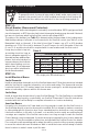
Temperature Typical Values
55°F (13°C) 17,000 ohms
65°F (18°C) 13,000 ohms
75°F (24°C) 10,000 ohms
85°F (29°C) 8,000 ohms
Table 3 - Floor Sensor
Resistance Values
STEP 1.3
Use a digital multi-meter set to the 200Ω or
2000Ω (2kΩ) range to measure the resistance
between the conductors of the mat power
leads. Record these resistances in Table 4
under “Out of the box before installation”.
The resistance should measure within the
resistance range on the nameplate label.
If it is a little low, it may be due to low air
temperatures or meter calibration. Consult
the factory if in doubt.
Measure the resistance between either of
the white or black leads and ground lead.
This measurement should be “open”, usually
indicated by an “OL” or a “I”. This is the same
as displayed when the test leads are not
touching anything.
If there is any change in the reading, record
this information and contact the factory before
continuing. This could indicate damage, test
lead problems, or a number of other issues.
Try “pinning” the test leads to the cable lead
wires against a hard non-metal surface if the
readings continue to fluctuate.
Change the meter to the 20,000 ohms (20 kΩ) range.
Measure between the lead wires of the control
sensor. This resistance varies according to the
temperature sensed. Table 3 provides approximate
resistance-to-temperature values for reference.