
Manual


SunTouch WarmWire Installation Manual 17
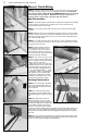
If plastic lath is used instead of the typical metal lath, the cable can be installed before pouring
the self-leveling mortar b ed.
CAUTION: If metal lath is used in the mor tar bed, do not allow the cable to come in direct con-
tact with the lath. Damage to the cable could result.
Self-leveling Mortar Beds. Self-leveling mortar beds are appropriate if installing non-masonry
floor coverings such as engineered wood, vinyl, laminate, or carpet. Attach the cables to the slab
or subfloor, then pour a 1/4”–1/2”-thick layer of self-leveling mortar over the cables according to
manufacturer’s specifications. Install the floor coverings after the mortar has cured.
Regardless of the type of mortar bed used in any particular application, always secure the cable
to the floor first, then cover it with the mortar or cement. Never attempt to lay or work the cable into
a previously-poured layer of wet mortar.
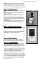
It is strongly recommended that tile and stone flooring be installed according to manufacturer’s
recommendations, Tile Council of North America (TCNA) guidelines, and ANSI specifications. Follow
industry and manufacturer’s recommendations when installing non-masonry floor coverings, such as
hardwood, vinyl, laminate, or floating floors.
Other Considerations
Expansion joints. In slab or mortar applications, do not install the cables through an expan-
sion joint unless an appropriate antifracture membrane is installed p er TCA recommendations. If not
using an antifracture membrane, install the cables right up to the joint, if necessary, but not through
the joint.
Mosaic tile. When laying mosaic tile, first embed the cables in the appropriate mortar bed as
shown in the diagrams on the previous pages, and allow to cure per manufacturer’s instructions.
Then thin-set the mosaic tile according to typical practice.
REMEMBER: If in doubt about any aspect or phase of the installation, consult with building
professionals and/or the manufacturer regarding specific installation details before
beginning.
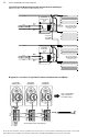
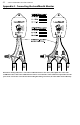
Typical Electrical Wiring Diagram with SunStat Control (120/240VAC)
Dedicated 120 or 240VAC, 20-amp (maximum) circuit.
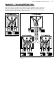
Typical Electrical Wiring Diagram with SunStat Control (120/240VAC)
Dedicated 120 or 240VAC, 20-amp (maximum) circuit.
Appendix 2: Typical Electrical Wiring Diagrams (120 and 240 VAC)
All electrical work must be done by a qualified licensed electrician in accordance with local building and electrical codes, and the
National Electrical Code (NEC), especially Article 424, Part IX of the NEC, ANSI/NFPA70 and Section 62 of CEC Part 1.
Ground
Black
Black
Black
White
White
White
Line 1
Load 1
Load 2
Line 2
120 VAC or 240 VAC
Sensor Wire
(no polarity)
120 VAC or 240 VAC Heating Cable
(maximum 15 amps)
Two or more120 VAC or
240 VAC Heating Cables
(maximum 15 amps)
CAUTION: Make sure 120 VAC
is supplied to 120VAC cables and
240VAC is supplied to 240VAC
cables. Otherwise, dangerous
overheating and possible fire
hazard can result.
120/240 VAC
SunStat Control
Ground
Black
Black
Black
White
White
White
Line 1
Load 1
Load 2
Line 2
120 VAC or 240 VAC
Sensor Wire
(no polarity)
120/240 VAC
SunStat Control
Ground
Black
Black
Black
White
White
White
Line 1
Load 1
Load 2
Line 2
120 VAC or 240 VAC
Sensor Wire
(no polarity)
120 VAC or 240 VAC Heating Cable
(maximum 15 amps)
Two or more120 VAC or
240 VAC Heating Cables
(maximum 15 amps)
CAUTION: Make sure 120 VAC
is supplied to 120VAC cables and
240VAC is supplied to 240VAC
cables. Otherwise, dangerous
overheating and possible fire
hazard can result.
120/240 VAC
SunStat Control
Ground
Black
Black
Black
White
White
White
Line 1
Load 1
Load 2
Line 2
120 VAC or 240 VAC
Sensor Wire
(no polarity)
120/240 VAC
SunStat Control