
Manual

SunTouch WarmWire Installation Manual 5
Sensor Resistance Log (page 6).
ALWAYS pay close attention to voltage and amperage requirements of the
circuit breaker, control, and the cable system. For instance, do not supply
240 VAC to 120 VAC controls and cables.
ALWAYS make sure all electrical work is done in accordance with local
building codes, the National Electrical Code (NEC), especially Article 424,
Part IX, and Section 62 of the Canadian Electrical Code (CEC) Part I.
Some Tips
Trowel. Use a plastic trowel(81007407) to reduce the possibility of
cable damage.
Insulation. The better insulation that is provided, the more efficiently
the system operates, and the better the floor is heated. Concrete slab sur-
faces offer the most thermal drain and should be insulated before applying
the cables, if at all possible. See “Phase 9: Install Insulation” as well as the
cross sec tions in Appendix 1.
Controls. The SunStat
™
controls will provide direct floor-warming con-
trol for better comfort. Other controls may not give the the same desired
level of control. Always select controls that will meet the voltage and
amperage ratings of the system and are designed for resistance heating
systems.
Mortars. Self-leveling mortars are b ecoming more popular to use
because of their ease of application over the cables. If laying tile, another
layer of thin-set will need to be applied in order to lay the tile. Always
use polymer-modified cement-based mortar. Do not use solvent-based
adhesives or pre-mixes because they are not as heat resistant.
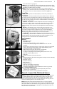
LoudMouth
™
. The LoudMouth sounds an alarm if damage occurs to
the cable during installation. The LoudMouth stays connected to the power
leads throughout cable and tile installation. A small screwdriver for con-
necting the leads is included with the LoudMouth monitor.
Items Needed
Materials:
• WarmWire system
• WarmWire strap
• Thermostat control with floor sensor (SunStat)
• 20-amp circuit breaker (single for 120-VAC and dual for 240-VAC
systems)
• Electrical box (extra deep) for the control; single-gang (not a gangable
type) or 4”-square deep box with a single-gang “mud ring” cover
• 4” junction box with a cover, if needed
• Cable clamps for junction box (for new construction)
• Flexible or rigid conduit (for new construction)
• 12-gauge or 14-gauge electrical wiring cable (consult lo c al code)
• Wire nuts if using a junction box
• Nail plate
• Polymer-modified cement based mortar
Tools:
• Digital multi-meter [for ohms testing; must read up to 20,000 ohms (Ω)
to measure sensor]
• Drill with 1/2” bit
• Hammer and chisel
• Wire strippers
• Phillips screwdriver
• Fish tape (for existing construction)
• Hole saw (for existing construction)
• Trowel (81007407-plastic preferred) with 3/8” notches (or greater)
Floor covering installation tools:
• Book or video on electrical wiring techniques, but professional
connection is recommended.
• Book or video on floor covering installation techniques
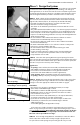
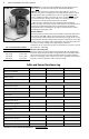
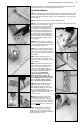
Phase 3: Inspect the Cable and Sensor
STEP 3.1 Take the cable out of the box and inspect it to make sure there
is no visible damage. There are shielded leads coming out of the spool
of cable called the “power leads” (they are simply power supply cables
that do not heat). The power leads are approximately 10 ft. long and will
connect the heating cable to the control for power.
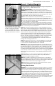
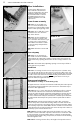
STEP 3.2 Record the product information. There is a factory-applied
nameplate label on the power leads. Do not remove this label. Record the
cable serial number, model number, voltage, and cable resistance range in
the Cable and Sensor Resistance Log (page 6). If installing more than one
cable, do this for each of them.
ALWAYS
STEP 3.1
STEP 3.2