
Manual

6 SunTouch WarmWire Installation Manual
IMPORTANT! To retain the Limited Warranty, the following measure-
ments must be recorded, and all steps of this manual followed.
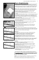
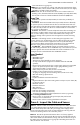
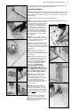
STEP 3.3 Take resistance readings of the cable and floor sensor to
make sure they are not damaged. It is very important that this b e done
throughout the entire installation process. Use a quality digital ohm-
meter or multimeter [able to measure up to 20,000 ohms (Ω)] to make
these measurements. Analog meters (that use a moving needle) are
not accurate for this product and should not be used.
Take resistance readings (1) before beginning the installation,
(2) after the cable and sensor are fastened to the floor, and (3) after floor
coverings are installed. Checking these measurements frequently
during finished floor installation is strongly recommended in order to
avoid burying a damaged cable.
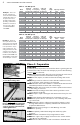
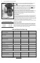
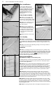
Check for Breaks
Measure resistance between the black and white cable leads (black and
blue leads for 240-VAC cables) and record this in the chart below. This
measurement should be within the cable resistance range shown on the
nameplate label. Measure between the lead wires of the floor sensor. This
resistance varies according to the temperature sensed in the tip. The sen-
sor resistance table at left provides approximate values for
comparison. A cut or break in the wire is indicated by a resistance of “infi-
nite” ohms (no continuity).
Check for Short-Circuits
Measure resistance between the black and ground leads and between
the white and ground leads (blue and ground leads for 240-VAC cables)
and record this value below. These measurements should be “infinite”
ohms (no continuity). A cut or pinch in the wire is typically indicated by a
resistance value less than the cable resistance range.
STEP 3.3
CABLE 1 CABLE 2 CABLE 3
Cable serial number
Cable model
Cable voltage
Factory cable resistance range
OUT OF THE BOX BEFORE INSTALLATION (ohms)
Cable black to white
Cable black to ground
Cable white to ground
Sensor wire
AFTER CABLE AND SENSOR ARE FASTENED TO FLOOR (ohms)
Cable black to white
Cable black to ground
Cable white to ground
Sensor wire
AFTER FLOOR COVERINGS ARE INSTALLED (ohms)
Cable black to white
Cable black to ground
Cable white to ground
Sensor wire
RETAIN THIS LOG TO RETAIN THE WARRANTY! DO NOT DISCARD!
Cable and Sensor Resistance Log
Floor Sensor Resistance Values
Temperature Typical Values
55°F (13°C) 17,000 ohms
65°F (18°C) 13,000 ohms
75°F (24°C) 10,000 ohms
85°F (29°C) 8,000 ohms