
Manual

SunTouch WarmWire Installation Manual 7
Phase 4: Electrical Rough-in
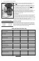
See wiring diagrams in Appendix 2 for different voltages and applications.
For additional help see www.suntouch.com.
New Construction (see below for existing construction)
OVERVIEW We recommend the floor-warming system be installed on a
dedicated circuit coming directly from the circuit breaker panel. Follow all
National Electric Code (NEC) and other local electrical code requirements
when installing this system. Work should be done with great care and with
the power turned off to the circuit being worked on.
STEP 4.1 Install a maximum 20-amp circuit breaker(s) into the breaker
panel, depending on the load of the system. Use a 120-VAC single-p ole
breaker for a 120-VAC system. Use a 240-VAC double-pole breaker for a 240-
VAC system. Use a Ground Fault Circuit Interrupter (GFCI) type if not using
our controls (which have a built-in GFCI).
For systems that are too large to directly power through one SunStat
but must be operated by one floor-sensing control, use a SunStat control
in combination with up to 10 SunStat Relay Controls. Contact a SunTouch
dealer or the factory for more information.
STEP 4.2 Install an electrical box for the control. If installing one to two
cables, use an extra-deep single-gang box to allow plenty of room for the
wiring. Use a 4”-square box if installing three cables. The box can be located
almost anywhere that is well ventilated. However, the best place is in the
same room as the cable, typically about 60” above the floor, and within
reach of the power lead wires of the cable. If installing more than three
cables, it will be necessary to connect their p ower leads in a junction box
first (see Step 4.4) to keep from overfilling the control electrical box. Then
route one power supply from this junction box to the control box.
See Step 5.23 for special requirements if the control will connec t to a
heating cable entering a shower area.
STEP 4.3 Following code, feed 14- or 12-gauge NM type electrical wiring
from the circuit breaker panel to the control electrical box. Leave about
6”–8” of extra wire extended from the box to work with.
STEP 4.4 If the control box must be mounted in a location that is too far
to reach with the power lead wires, it will be necessary to mount a junction
box where the lead wires can be terminated. Use a standard junction box
with a cover, mounting it below the floor, in the attic, or in another easily
accessible location. It must remain easily accessible and not located behind
a wall, cabinet, or similar obstruction. Then use 14- or 12-gauge NM type or
other accepted electrical wiring to connect from the junction box to the
control box.
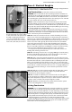
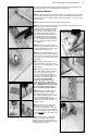
STEP 4.5 Drill two 1/2” holes in the baseplate directly below the control
electrical box. Then, as close to the flo or surface as possible, drill two
horizontal holes, intersecting the top holes.
STEP 4.6 If conduit is required by local electrical code, cut a length of
1/2” to 3/4” electrical conduit to run from the control box down to the base-
plate. At the baseplate it may be necessary to chisel out more of the wood
to make it easier to feed the wires up through the conduit.
STEP 4.7 Mark the circuit breaker in the panel which feeds the system
with “Floor warming/bath” or similar description.
Existing Construction
OVERVIEW It is recommended that the system be installed on a separate,
dedicated circuit coming directly from the breaker panel. In existing con-
struction, however, it may be difficult to do this depending on the location
of wiring and the breaker panel. Tapping off an existing circuit may be pos-
sible, but only if there is enough load capacity to handle both the system
and any additional loads that may be placed on the circuit. Keep in mind
that typical hair dryers can pull up to 10 amps (1200 watts) of load.
Follow all NEC and other local electrical code requirements when install-
ing this system. Work should be done with great c are and with the power
turned off to the circuit being worked on.
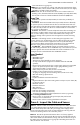
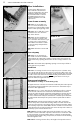
STEP 4.2
Install an extra-deep single-gang
box if connecting one or two cables
to the control. Use a 4”-square deep
box with a single-gang mud ring
cover if connecting three cables,
because the extra room is needed
for the wire, wire nuts, and control.
STEP 4.5