
Manual

8 SunTouch WarmWire Installation Manual
STEP 4.8 Install a maximum 20-amp circuit breaker(s) into the breaker
panel, depending on the load of the system. Use a 120-VAC single-p ole
breaker for a 120-VAC system. Use a 240-VAC double-pole breaker for a
240-VAC system. Use a Ground Fault Circuit Interrupter (GFCI) type if
not using one of our controls (which have a built-in GFCI).
For systems that are too large to directly power through one SunStat
but must be operated by one floor-sensing control, use a SunStat
Control in combination with up to 10 SunStat Relay Controls. Contact a
SunTouch dealer or the factory for more information.
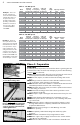
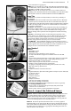
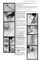
STEP 4.9 Cut an opening in the wall for the control electrical box.
If installing one to two cables, use an extra-deep single-gang box to
allow plenty of room for the wiring. Use a 4”-square box if installing
three cables. The box can be located almost anywhere that is well venti-
lated. However, the best place is in the same room as the cable, typically
about 60” above the flo or, and within reach of the power lead wires of
the cable. If installing more than three cables, it will be necessary to
connect their power leads in a junction box first (see Step 4.11) to k eep
from overfilling the control b ox. Then route one power supply from this
junction box to the control box. See Step 5.23 for special requirements
if the control will connect to a heating cable entering a shower area.
STEP 4.10 Following code, feed 14- or 12-gauge NM type electrical
wiring from the circuit breaker panel to the control electrical box
opening. Leave about 6”–8” of extra wire extended from the opening.
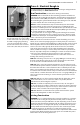
STEP 4.11 If the control box must be mounted in a location that is
too far to reach with the power lead wires, it will also be necessary to
mount a junction box where the lead wires can terminate. Use a
standard junc tion box with a cover, mounting it below the floor, in
the attic, or in another easily accessible location. It must remain easily
accessible and not located behind a cabinet or similar obstruction. Then
use 14- or 12-gauge NM type or other accepted electrical wiring to con-
nect from the junction box to the control electrical box.
STEP 4.12 At the floor level below the control box, cut a 2”x 2”-wide
piece from the wall surface. Use a wood chisel to notch out a channel in
the baseplate to make it easier to route the wires up the wall.
STEP 4.13 Mark the circuit breaker in the panel which feeds the
system with “Floor warming/bath” or similar.
Phase 5: Install the Cables
Getting Started
IMPORTANT! Refer to Phase 8 and Appendix 1 to make sure the
floor is properly prepared for installation of the cable(s), especially
the use of reinforcement, leveling, and insulation on concrete slab.
STEP 5.1 Use the sketch and design considerations made earlier in
Phase 1 to begin laying the cables. Do not install the cables closer
than about 6” from wax toilet rings and plumbing to keep from over-
heating these items.
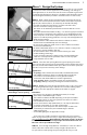
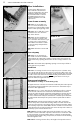
STEP 5.2 Make sure to space the cables to provide the warmth
desired. NE VER space them at 1” apart because this will cause a very
hot area and may damage the system. Before installing the cables, make
certain the proper cable length and voltage has been selected for the
square footage to be heated .
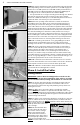
STEP 5.3 If this is new construction, draw lines on the floor or use tem-
plates to outline the area of any cabinets, fixtures, or future walls that
will be placed in the room. NEVER install the cables under cabinets, fix-
tures, or walls. Excess heat may
build up under these items and
cause damage.
STEP 5.4 Decide which direc-
tion the cables will run on the
floor for the easiest coverage.
Refer to the sample layouts
in this manual for assistance.
Depending on the shape of the
area, it may help to think of it in
terms of several smaller areas.
NEVER cross the cables over each other or cut them shorter. Damage
STEP 4.10
STEP 4.12
STEP 5.3
STEP 4.11
STEP 4.9
NEVER use 1”
spacing
NEVER use less than 2” spacing.
NO!