
Manual


18 SunTouch Space Warming Manual
If problems arise with the SunTouch floor-warming mat or its related electrical com-
ponents, please consult this troubleshooting guide. If not qualified to perform electrical
work, it is highly recommended that a qualified, licensed electrician be hired.
Any electrical troubleshooting work should be performed with the power
removed from the circuit, unless otherwise noted.
Although this troubleshooting guide is provided to assist with problems experienced
with a SunTouch floor-warming system, results are never guaranteed. SunTouch does not
assume any liability or responsibility for damage or injury that may occur from using this
guide. If problems with the system persist, call the manufacturer at 888-432-8932.
Appendix 5. Troubleshooting Guide
Problem
Mat resistance measurement is
outside the range printed on the name-
plate label.
Floor is not getting warm.
Floor heats continuously.
Floor temperature shows “HI” or may
show temperature over 100°F.
Control is not working correctly.
Control is not working at all.
GFCIconflictsandfalse-trips
Possible Cause
An analog ohmmeter (using a moving needle)
was used to take the reading.
If measurement shows an open or short circuit,
the heating wire has been damaged.
If measurement is just a little low or high, room
temperature has affected the resistance.
The resistance measurement could be from more
than one mat wired in series, or wired in parallel.
Either will provide false resistance
readings.
The ohmmeter may be set to the wrong scale.
Forinstance,the200Kohmsscalemeasuresup
to 200,000 ohms.
Mat has been damaged.
GFCIhastripped,indicatedbyalightonthe
control.Lightmaybelabeled“GFI”,maybe
below the words “Stand by”, or on the button
labeled “Test”.
Incorrect voltage supplied, or mismatched
electrical components used.
Concrete slab floor.
Mats are wired in “series” or “daisy chained”
(end-to-end).
Sensor is loose or broken. If control has a
digitaldisplay,itmayindicate“LO”.
Incorrect wiring. The control was “bypassed”
when it was wired to the power supply.
Defectivecontrol.
Floor sensor is not wired properly, or is located
incorrectly.
If a programmable control, the programming
may be incorrect.
Incorrect voltage supplied, or mismatched com-
ponents used.
Floor sensor is not wired properly, or is not
working properly.
Looseconnection(s)onlinesideand/orloadside
of control.
Defectivecontrol.
No power is supplied.
Floor sensor is not wired properly, or is not
working properly.
Defectivecontrol.
MorethanoneGFCIonthecircuit.
An electric motor or a ballasted light source is
sharing the circuit with the mat.
Solution
Obtain a digital ohmmeter able to read 0 to 20,000 ohms and remeasure the resistance.
Record resistance between all wires and contact the manufacturer.
Maketheroomtemperature75°–85°F,orcontactthemanufacturer.
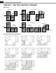
Make sure resistance measurements are for only one mat at a time. When connecting more
than one mat to the control, multiple mats must be wired in parallel (i.e., black to black,
white to white).
The ohmmeter should typically be set to the 200 ohms scale, with the exception of mats having
a rating above 200 ohms on their nameplate label. If the resistance reading is outside the range
printed on the nameplate label, contact the manufacturer.
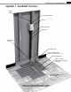
Measure mat resistance. Check for both “open circuit” and “short circuit” as detailed earlier in this
manual. If damaged, record resistances between all wires and contact the manufacturer.
Checkforloosewireconnections.ResettheGFCIonthecontrolorcircuitbreaker.Ifittripsagain,
check for a short circuit in the mat as detailed earlier in this manual. If mat is damaged, record
resistancebetweenallwiresandcontactthemanufacturer.Ifmatisnotdamaged,replacetheGFCI
control.Alsosee“GFCIconflicts”below.
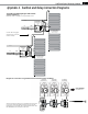
Measure “line” voltage, then measure “load” voltage. Both 120-V mats and controls have black and
white leads. 240-V mats have black and blue leads, and 240-V controls have black and red leads.
Surface temperatures rise slowly in a slab. If, after 5 to 8 hours of heating, the floor is not warmer
to the touch, check for mat damage (see “Mat has been damaged” above). Measure “load”
voltage/amperage to mat.
Multiple mats must be connected in “parallel” (or black-to-black, white-to-white).
SunTouch controls have a floor sensor. Pull the sensor wires loose from the control and rein-
sert them. If this does not solve the problem, measure resistance across the sensor wires. For a
SunTouch control the resistance should be between 17,000 ohms (at 55°F) and 8,000 ohms (at
85°F). See sensor wire resistance values on page 4.
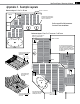
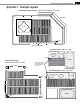
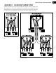
Make sure wiring connections are correct. Consult the wiring diagram on the back of the control,
the instructions that came with the control, or the wiring diagram in this manual.
Return control to dealer for replacement.
Make sure only one floor sensor is connected to the control. Also see “Sensor is loose or
broken” above.
Carefully read and follow control programming instructions.
Test voltage, verify parts. See “Incorrect voltage supplied” above.
Make sure only one floor sensor is connected to the control. Also see “Sensor is loose or
broken” above.
Remove and reinstall the wire nuts at each connection. Make sure the wire nuts are tight.
Check all connections back to the breaker.
Return control to dealer for replacement.
Check circuit breaker. Measure voltage at the control. Check all connections between breaker
and control.
Make sure only one floor sensor is connected to the control. Also see “Sensor is loose or
broken” above.
Return control to dealer for replacement.
GFCIunitswillsometimestripwhenthereisnothingwrongwiththeequipmentonthecircuit,
butwhenthereismorethanoneGFCI.ReroutepowertoavoidhavingmorethanoneGFCIon
the circuit.
ElectricmotorsandotherelectricaldevicescancauseaGFCItofalse-trip.Runadedicatedcircuit
to the floor-warming system.