TapeMat ® Installation Manual Series D12, C12 & C15 Assembled in the USA Includes Custom TapeMat® and ShowerMat™ Please be aware local codes may require this product and/or the thermostatic control to be installed or connected by an electrician. Please leave this manual with the end user.
Read this Manual BEFORE using this equipment. Failure to read and follow all safety and use information can result in death, serious personal injury, property damage, or damage to the equipment. Keep this Manual for future reference. Floor heating mats are a simple way to heat an indoor space. This instruction manual is provided as a guide to installing TapeMats, including design considerations, installation steps, limitations, precautions, and floor covering guidelines.
Expected floor temperature Heating performance is never guaranteed. The floor temperature attainable is dependent on how well the floor is insulated, the temperature of the floor before start up, and the overall thermal drain of the floor mass. Insulation is required for best performance. Refer to Phase 4 for important design considerations. These are the three most common installations: 1.
Table 1 As with any electrical product, care should be taken to guard against the potential risk of fire, electric shock, and injury to persons. The following cautions must be observed: Local building or electrical codes may require modifications to the information provided. You are required to consult the local building and electrical codes prior to installation. If this information is not consistent with local building or electrical codes, the local codes should be followed.
ALWAYS make sure all electrical work is done by qualified persons in accordance with local building and electrical codes, Section 62 of the Canadian Electrical Code (CEC) Part I, and the National Electrical Code (NEC), especially Article 424. ALWAYS use copper only as supply conductors to the thermostat. Do not use aluminum. ALWAYS seek help if a problem arises.
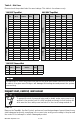
Table 2 - Mat Sizes Please check the product label for exact ratings. This table is for reference only. 15 20 25 30 45 60 3' x 5' 3' x 6'-8" 3' x 8'-4" 3' x 10' 3' x 15' 3' x 20' 240 VAC TapeMat Model Number 12000524 12000724 12001024 12001224 12001524 12001724 12002024 12002224 12002524 12003024 12003524 12004024 12004524 12005024 12000536 12000636 12000836 12001036 12001536 12002036 Amp Ohms Draw 1.0 109 - 134 1.5 76 - 94 2.0 57 - 71 2.5 43 - 54 3.0 34 - 42 3.5 29 - 36 4.0 25 - 32 4.5 22 - 28 5.
STEP 1.2 Record the product information in Table 4. Give this information to the homeowner to keep in a safe place. The Mat model number, serial number, voltage, and resistance range are shown on a nameplate label attached to the power leads. White or Blue Lead Ground Lead Black Lead Black wire to COM Red wire to Ω Do not remove this nameplate label. The electrical inspector will need to see this. STEP 1.
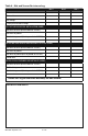
Table 4 - Mat and Sensor Resistance Log Mat 1 Mat serial number Mat model Mat voltage Factory mat resistance range OUT OF THE BOX BEFORE INSTALLATION (OHMS) Mat black to white (black to blue for 240VAC) Mat black to ground Mat white to ground (blue to ground for 240VAC) Sensor wire AFTER MAT AND SENSOR ARE FASTENED TO FLOOR (OHMS) Mat black to white (black to blue for 240VAC) Mat black to ground Mat white to ground (blue to ground for 240VAC) Sensor wire AFTER FLOOR COVERINGS ARE INSTALLED (OHMS) Mat black
Phase 2 - Electrical Rough-in To prevent the risk of personal injury and/or death, make sure power is not applied to the product until it is fully installed and ready for final testing. All work must be done with power turned off to the circuit being worked on. STEP 2.1: Circuit Breaker (Overcurrent Protection) TapeMat(s) must be protected against overload by a circuit breaker.
STEP 2.3: Bottom Plate Work Drill or chisel holes at the bottom plate as indicated. One hole is for routing the power lead conduit and the other is for the thermostat sensor. These holes should be directly below the electrical box(es). Power lead conduit Wire Clip Sensor wire If going in to an existing wall, cut out dry wall and chisel out bottom plate to route wires to control. Power lead Sensor wire STEP 2.
Phase 3 - Mat Installation STEP 3.1: Floor Cleaning The floor must be completely swept of all debris including all nails, dirt, wood, and other construction debris. Make absolutely sure there are no objects on the floor which might damage the TapeMat wire. Wet mop the floor at least twice to ensure there is no dirt or dust. This will allow proper bonding of the mortar. STEP 3.2: Position the Power Leads Carefully cut the tie binding the power lead coil. Do not nick the braid covering the power lead.
STEP 3.4 Test Fit the Mat Roll out the mat, flipping it as needed to cover the intended area. This is very important to ensure proper fit before proceeding. If there is too much mat for the area it cannot be cut shorter and heating wire cannot be routed into a wall, under baseboards, or other similar areas. All heating wire must be embedded in the floor mortar. STEP 3.
Cu t ma t Use hot glue to attach wire to the floor. M remat m ov esh ed Roll over Roll-over Turn. Fill-in Technique. Installing in front of cabinets and toilets: Install mat right up to the face of the cabinet as shown above. Mat can be installed under tile to within 6" from the wax ring, and can slightly underlay the foot of the toilet if need be (approximately 20" from wall).
STEP 3.6 Secure the Mat to the Floor Lay the mat down flat. Ensure it fits well and has no folds or large ripples. Securing the mat as flat as possible will help make a smooth surface for spreading mortar. Chisel a path for the power lead and factory splice. If the mat comes with double-sided tape already attached, remove the liner along one edge and press the tape down. Remove the liner along the other edge and press the tape down, pulling lightly on the mat to keep it flat.
Conduit Power Lead Factory Splice (in thin-set, not in conduit) Tape Sensor Heating Wire Top-Down view of Mat and the sensor entering wall. STEP 3.9 Feed the sensor wire to the SunStat thermostat electrical box leaving at least 6"-8" of free lead length in the box. Weave the sensor at least 1' into the mat area, halfway between the heating wires, and secure it using hot glue. Do not cross the heating wires.
STEP 3.10: Shower Application Acceptance of this application must be verified by the local inspector or authority having jurisdiction (AHJ). Locate power lead and factory connection to heating wire at least 1’ outside the shower area. Shower Curb Tile Avoid sharp bends in heating wire Thin-set Mortar Factory Splice Heating Wire 1. 2. 3. 4. Refer to diagrams in the Appendix, especially pages 26 & 27. Never install TapeMat or ShowerMat in shower walls (or any other wall).
Take photographs of the mat installation. This can be very useful later during remodel work to help avoid possible wire damage. Keep the photos with this installation manual and provide to end user upon completion. Phase 4 - Floor Coverings It is recommended to consult with professional flooring installers to make sure proper materials are used and proper installation techniques are followed.
Type of Construction Mortar Applications: Thin-set and thick-set (self-leveling) mortar applications are illustrated below and to the right. a. If a backer board or plywood sheeting is used to strengthen the floor, or if the mat will be placed directly onto the slab, install TapeMat in the thin-set mortar bond coat above these materials. b.
CEMENT BACKERBOARD OVER FRAME FLOOR Tile/stone or laminate flooring Thin-set TapeMat Cement backerboard, thick-set, or selfleveling mortar bed Insulation (per International Residential Code, Chapter 11) THIN-SET OVER SLAB ON GRADE Tile/stone or laminate flooring Thin-set or selfleveling mortar bed TapeMat Crack isolation membrane /Insulating barrier Concrete slab with rewire or rebar Insulation (per International Residential Code, Chapter 11) 19 of 36 © 2014 Watts Water Technologies
Phase 5 - Control Installation STEP 5.1: Install the Controls If it has not already been done, install an electrical box for the SunStat thermostat and SunStat Relay. See Step 2.2 for details. STEP 5.2 Refer to the wiring diagrams in the Appendix of this manual for typical configurations. STEP 5.3 Read and follow the instructions included with the SunStat thermostat and SunStat Relay for complete connection instructions, requirements, and mounting. STEP 5.
Power supply Electrical box Single-gang Mud Ring (if required) SunStat Thermostat Electrical conduit Sensor wire Mat power lead Heating Wire Mat Mesh Bottom plate cut-outs Sensor installed in floor (equal distance between two heating wires) Thin-set, thick-set, thin-slab, or self-leveling mortar bed Tile, stone, or laminate floor covering General layout of the TapeMat installation 21 of 36 © 2014 Watts Water Technologies
Appendix Types of turns Roll-over Turn 180° or Back-to-Back Turn 90° Turn 90° Flip Fill-in Technique IOM-WR-TapeMat 1425 22 of 36
Step-by-step layout for a typical bathroom 1. 2. 3. 4. 5. 6. 7. 8.
Bathroom layout: One mat Shower Install 4"–6" from walls. Control 20" Toilet Install mats 6" away from wax ring (approximately 20") from back wall. Vanity Closet Install mats right up to the face of the cabinet. The heat only conducts about 1-1/2" from the wire.
Front entryway layout: Three mats Front Entryway Doorway Doorway Control Small bath layout: One mat Install mats 6" away from wax ring (approximately 20") from back wall. Sink Control Bath Tub Install mats right up to the face of the vanity. The heat transfers only about 1-1/2" from the wire.
Bathroom layout: Three mats Install mats 6" away from wax ring (approximately 20") from back wall. 20" Mat Toilet Do not begin the mat inside the shower area. The controls should NEVER be installed in the shower area, or where anyone in the shower could touch the controls. Install the controls a minimum of 4' away from the shower area. Vanity Shower Doorway Control Control Toilet Bath Tub Fill in triangular areas by removing wire from mat and securing with hot glue.
See Phase 3 for complete details and Cautions. This application into a shower area must be verified by the local inspector or the authority having jurisdiction. Shower installation detail Never install the mat in shower walls (or any other walls). Heating Wire Factory Splice Locate power lead and factory connection to heating wire at least 1’ outside the shower area. Avoid sharp bends in heating wire Use an s-shaped curve.
120/240VAC Control Wiring Diagrams Typical Wiring for one Mat with SunStat Control (120/240VAC) 20-amp circuit. Heating Mat (maximum 15 amps) Ground 120/240 VAC Control Load 1 Black Black Line 1 Black Sensor Wire (no polarity) Sensor 120 VAC or 240 VAC Bus White Line 2 White A B Load 2 White 120 VAC or 240 VAC Heating Mat (maximum 15 amps) Typical Wiring for multiple Mats with SunStat Control (120/240VAC) 20-amp circuit.
SunStat Relay Connection Diagrams Typical Wiring for SunStat with SunStat Relay(s) 20-amp circuit for each SunStat Control and SunStat Relay Ground 120/240 VAC Control Load 1 Black Black Line 1 Black Sensor 120 VAC or 240 VAC Bus White Line 2 White Two or more 120 VAC or 240 VAC Heating Mats (maximum 15 amps) A B Load 2 White Use size 18- to 24-gauge 2 conductor wire up to 100 feet (30 m) in length to connect Control to Relay.
Diagram for connection of signal wire between SunStat Control and Relays 120/240 VAC Control 120/240 VAC Relay 120/240 VAC Relay Up to 10 Relays can be connected to one Control Sensor Observe polarity when connecting relays All electrical work must be done by a qualified licensed electrician in accordance with local building and electrical codes, and the National Electrical Code (NEC), especially Article 424 of the NEC, ANSI/NFPA70 and Section 62 of CEC Part 1.
Connecting Multiple Mats To prevent the risk of personal injury and/or death, do not perform any electrical work unless qualified to do so. Work should be done with great care and with power turned off to the circuit being worked on. Follow all local building and electrical codes.
Troubleshooting Guide If problems arise with the TapeMat or its related electrical components, please consult this troubleshooting guide. If not qualified to perform electrical work, it is highly recommended that a qualified, licensed electrician be hired. Any electrical troubleshooting work should be performed with the power removed from the circuit, unless otherwise noted.
Problem Floor heats continuously. Control is not working correctly. Possible Cause Solution Make sure wiring connections are correct. Consult Incorrect wiring. The control was the wiring diagram on the back of the control the “bypassed” when it was wired to instructions that came with the control, or the wiring the power supply. diagram in this manual. Defective control. Return control to dealer for replacement. If a programmable control, the Carefully read and follow control programming instructions.
Electric Floor-warming Products 25-year Limited Warranty SunTouch and Watts Radiant (the Companies) warrant their respective electric floor heating mats and cables (the Products) to be free from defects in materials and workmanship for twenty-five (25) years from the date of manufacture. Thermostats and controls sold by the Companies are warranted, parts and materials, for two (2) years from the date of purchase. The sole remedy for controls is product replacement.
Notes 35 of 36 © 2014 Watts Water Technologies
Affiliations: SunTouch Customer Support USA Toll-free: (888) 432-8932 USA Fax: (417) 831-4067 Canada Toll-free: (888) 208-8927 Canada Fax: (905) 332-7068 Latin America Tel: (52) 81-1001-8600 Latin America Fax: (52) 81-8000-7091 SunTouch.com The SunTouch and Watts Radiant manufacturing facility’s Quality System is an ISO 9001:2008 registered facility through LRQA. 8 40213 11331 IOM-WR-TapeMat 1425 Watts Radiant Customer Support USA Toll-free: (800) 276-2419 USA Fax: (417) 864-8161 WattsRadiant.