
Install Instructions


Monitor the Wire!
Throughout the installation process
it is very important to take resistance
readings of the mat and floor sensor
wires to make sure they have not
been damaged. Use a quality digital
ohmmeter (multi-meter) able to mea-
sure up to 20,000 ohms (W) to take
these readings. Analog meters (with
the moving needle) are not accurate
enough for this product.
Use the LoudMouth
™
Monitor
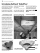
The LoudMouth is designed to monitor
the mat during the installation process.
If the heating wire is cut or damaged
during installation, this device sounds
an alarm. Ask about purchasing this
valuable tool.
SunTouch UnderFloor Installation Manual
5
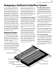
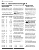
MAT 1 MAT 2 MAT 3
Mat Serial Number
Mat Size
Mat Voltage
Factory Mat Resistance Range
OUT OF THE BOX BEFORE INSTALLATION (ohms)
Mat black to white
Mat black to green
Mat white to green
Sensor Wire
AFTER SENSOR AND MAT ARE INSTALLED IN JOIST BAY (ohms)
Mat black to white
Mat black to green
Mat white to green
Sensor Wire
AFTER INSULATION IS INSTALLED (ohms)
Mat black to white
Mat black to green
Mat white to green
Sensor Wire
Note: Wire colors listed are for 120-VAC mats. See directions above for the 240-VAC color combinations to check.
RETAIN THIS LOG TO RETAIN THE WARRANTY! DO NOT DISCARD!
MAT AND SENSOR RESISTANCE LOG
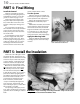
PART 1: Inspect the Mat and Sensor
Essential Product Information
and Warranty
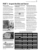
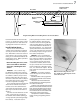
Do not remove the nameplate label
from the power leads (see photo).
Record the serial number, mat size,
voltage, and mat resistance range into
the resistance log below for each mat
and sensor wire.
To retain the Limited Warranty these
items and the following resistance
measurements MUST be recorded,
as well as all steps of this manual
followed. Refer now to the Limited
Warranty on the back cover of this
manual for complete requirements.
Measurements
At the very least, take resistance read-
ings (1) before beginning installation,
(2) after the mat and sensor have been
installed in the joist bay, and (3) after
insulation is installed.
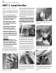
Checking for Breaks
Measure resistance between the
black and white leads (black and blue
leads for 240-VAC mats) and record this
below. This measurement should be
within the range shown on the name-
plate label. A cut or break in the wire
is indicated by a resistance of “infinite”
ohms (no continuity, or “OL” for “open
line”).
Checking for Short-Circuits
Measure resistances between the
black and green leads and between
the white and green leads (blue and
green leads for 240-VAC mats) and
record these below. These measure-
ments should be “infinite” ohms (no
continuity or “OL” for “open line”). A
cut or pinch in the wire is indicated by
a resistance value greater than zero but
less than the mat resistance.
If the resistance is not correct, or
if the wire has been cut or damaged,
note the damaged area and call the
factory for further instructions.
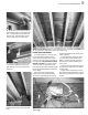
Checking the Floor Sensor
The SunStat controls come with a
floor sensor. This must be tested prior
to installation. Use a quality
digital ohmmeter that is capable of
measuring at least 20,000 ohms (W),
and measure between the lead wires
of the sensor. The measurement varies
according to the temperature sensed
in the tip. The sensor resistance table
on page 6 gives a set of approximate
values for comparison.
If no resistance is detected, or if the
resistance value is very different from
that shown in the sensor resistance
table, check the ohmmeter first to
make sure it was correctly set. Then
contact the factory for assistance.
Record the information from this nameplate
label into the Mat and Sensor Resistance Log
provided at right. Leave this nameplate label
attached to the power leads for later inspection.
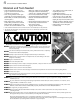
This Electric Radiant Heating Warning Label
must be cut out and taped near, or on the face
of the control.
To retain the Limited Warranty, resistance
readings and other data MUST be recorded in
the Mat and Sensor Resistance Log below. Use
the LoudMouth (right) to monitor the mat dur-
ing the entire installation process.
The LoudMouth
Measure resistances