
Install Instructions


Circuit Overcurrent Protection
and GFCI Protection
The SunTouch mat must be pro-
tected by a ground fault circuit inter-
rupter (GFCI). If the mats are directly
powered through the SunStat controls,
these already have an integral GFCI to
protect the mats (do not install a GFCI
6
SunTouch UnderFloor Installation Manual
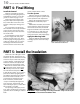
PART 2: Electrical Service Rough-in
type circuit breaker to supply a SunStat
Control because the respective GFCIs
may conflict and cause problems). If a
different type control or relay is used
that does not have a built-in Class A
GFCI, an indicating-type GFCI circuit
breaker must be used to protect the
mats. This GFCI breaker serves as a
local disconnect.
NOTE: Follow all local building
and electrical codes.
It is recommended that the system
be installed on its own dedicated cir-
cuit, directly from the circuit breaker
panel. However, small systems may
be able to tap into an existing circuit.
Consult an electrician. Make sure there
is adequate capacity for the mat(s) as
well as any other items that may use
this circuit. The mat(s) should not be
installed in a circuit with another GFCI
(breaker or outlet), lighting circuit (low-
voltage, halogen, or other types that
use ballasts or transformers that can
interfere), or motor circuit (exhaust fan,
hot tub, etc.) due to possible interfer-
ence which can cause the GFCI on the
control to false-trip.
The circuit breaker protecting the
mat(s) must be no larger than 20 amps.
Load the circuit breaker with no more
than the following: 12 amps on a
15-amp circuit breaker, 16 amps on a
20-amp circuit breaker. Additional
circuit breakers will be required for
larger loads than these.
Select mats so that no more than
15 amps are run through a SunStat or
SunStat Relay control.
Large Systems on one
Floor-sensing Control
For systems that are too large to
directly power through one SunStat,
but must be operated by one floor-
sensing control, use the SunStat
/SunStat Relay for best performance.
Contact a SunTouch dealer or the fac-
tory for more information.
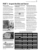
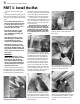
Install Electrical Boxes
SunStat box. Decide on the
location for the floor-sensing control.
Usually this will be in the same room as
the floor being warmed, but it can be
mounted almost anywhere as long as it
is not in a confined space where airflow
is restricted. To reach this box with the
mats, the mat power leads and the sen-
sor wire leads can both be extended if
needed with the appropriate size wire
at a junction box.
The control electrical box may be
a single-gang plastic deep box, but
be sure to follow all electrical code
requirements for box fill, grounding,
etc. when determining the correct box
for a particular application.
The control box should be located
on interior walls, typically 60” from the
floor, according to code requirements.
NOTE: The SunStat sensor wire
can be up to 50 ft. long, extended
with 22- or 24-AWG wire.
SunStat Relay boxes. The SunStat
also may be used as a master to control
SunStat Relays. The SunStat Relays
may be located most anywhere as long
as they are not in a confined space
where airflow is restricted. To reach
these controls with the mats, the mat
power leads should first go to a junc-
tion box (see page 9) and then to a
relay. (see instructions provided with
the SunStat Relay controls). There is no
floor sensor for these relays.
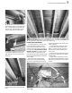
Other junction boxes: It is highly
recommended that a separate steel
electrical junction box be mounted
below the subfloor or in the wall in a
location to which the mat power leads
can be routed. A separate wiring drop
can be made from the control box
down to this junction box. This makes
it much easier to install the system.
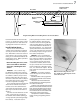
Bottom Plate Work
Drill a hole up through the wall
bottom plate to route the power wiring
from the control box to the mats below
the floor.
Rough-in Wiring
Install electrical wiring from the
power source breaker to the control
electrical box, and then to the junction
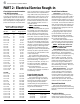
UnderFloor Mat Sizes, Amperage
Draw, and Resistance Ranges.
Amperage Resistance
Mat Size Draw Range (ohms)
120 VAC
12” x 5.5 ft. 0.4 247–302
12” x 8 ft. 0.6 167–204
12” x 10.5 ft. 0.9 121 –148
12” x 13 ft. 1.1 97–119
12” x 16 ft. 1.3 80–98
12” x 19 ft. 1.5 67–82
16” x 4 ft. 0.4 258–315
16” x 6 ft. 0.6 173–211
16” x 8 ft. 0.8 126–154
16” x 9.5 ft. 1.0 101–123
16” x 12 ft. 1.3 82–101
16” x 14 ft. 1.5 69–85
16” x 16 ft. 1.7 63–78
16” x 18 ft. 1.9 53–65
16” x 19.5 ft. 2.1 45–56
19.2” x 4.5 ft. 0.7 170–207
19.2” x 6.5 ft. 0.9 127–155
19.2” x 8 ft. 1.0 103–126
19.2” x 9.5 ft. 1.3 83–102
19.2” x 11.5 ft. 1.5 71–87
19.2” x 13 ft. 1.7 63–78
19.2” x 14.5 ft. 1.8 54–66
19.2” x 16 ft. 2.1 45–56
240 VAC
12” x 10.5 ft. 0.4 500–611
12” x 16 ft. 0.6 336–411
12” x 21 ft. 0.9 243–297
12” x 26 ft. 1.1 195–238
16” x 8 ft. 0.4 521–636
16” x 12 ft. 0.6 362–443
16” x 16 ft. 0.8 253 –310
16” x 19.5 ft. 1.0 207–253
16” x 24 ft. 1.3 168–206
19.2” x 6.5 ft. 0.4 526–643
19.2” x 9.5 ft. 0.6 359–439
19.2” x 13 ft. 0.9 256–313
19.2” x 16 ft. 1.0 207–253
19.2” x 19 ft. 1.3 167–204
19.2” x 23 ft. 1.5 143–174
19.2” x 26 ft. 1.7 127–156
Floor Sensor Resistance Values
Temperature Typical Values
55°F (13°C) 17,000 ohms
65°F (18°C) 13,000 ohms
75°F (24°C) 10,000 ohms
85°F (29°C) 8,000 ohms