
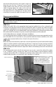
specific installation instructions

17 of 36 © 2014 Watts Water Technologies
Phase 4 - Finish Wiring
STEP 4.1
Feed the power leads from the cable up
through the hole drilled in the baseplate, or
up into the conduit to the control electrical
box (or junction box if one was used).
STEP 4.2
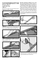
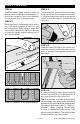
Below the control, or wherever the floor sensor
is to be located, measure at least 1 ft. into
the heated area. Mark the spot where the
sensor will be attached to the floor. Be sure
to locate the sensor exactly between two of
the heating cables.
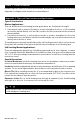
STEP 4.3
To make sure the sensor tip does not create
a high spot in the floor, it may be necessary
to chisel a channel into the floor and lay the
sensor tip into the channel. Hot glue the tip
into place.
STEP 4.4
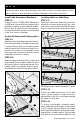
Feed the sensor wire up to the control box.
Finish by securing a steel nail plate over the
wires to protect them against baseboard
nails later.
STEP 4.5
If it was necessary to end a power lead at a
junction box, feed 14- or 12-gauge electrical
wire from this box to the control box.
Tip: If more than one cable was installed,
label the ends of the power leads with a brief
description as to which area they supply power.
Use tape to label them “Cable 1,” “Cable 2,”
“Kitchen,” “Bath,” or similar. This will make
it easier to identify the leads later on. Take
photos of the installation. This will provide a
useful record for any future needs.
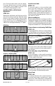
Sensor over RPM Mat
Sensor over Schluter® DITRA-HEAT Membrane