
Wiring Guide
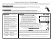
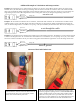
Table Of Contents

Additional Examples of Calculations and Interpretations:
Example: The Fault Finder gives a readout of 187 feet, minus 7 feet of power leads, 180 feet, but the cable is only 165 feet long.
180-165=15 feet, the meter detects some type of damage about 15 linear feet from the far end of the cable. If the readout from the
other power lead indicates damage substantially less than 150 feet from the start of the cable, there may be two areas of damage to a
single heating element of the cable. Diagram below is of a heating cable with one cut through a single heating element wire.
power lead
power lead
ground
heating cable
one wire cut
Example: “R” calculated to be 24.6 Runs for one conductor, and from the other conductor “R” calculated to be 25.3 Runs. This is
within the margin of error of the Fault Finder, and often an indication of a single point of damage to both heating elements of the
cable, as shown in diagram below. 24.6 Runs x 3” spacing = 73.8” (Linear distance) from the first cable “Run” to the damaged area.
power lead
power lead
ground
heating cable
a cut through the cable
Example: Your ohm meter shows continuity between both power leads and the ground wire. The damage is causing a short to ground,
as shown in the diagram below. “R” calculated to be about 27 Runs for each conductor, 27 x 2.5”spacing = 67.5” (“L”). You would
measure 67.5 inches out from the start of your cable weaving pattern to determine the approximate area of the damage to this cable.
power lead
power lead
ground
heating cable
short to ground
Pictures of the Fault Finder in use
This shows the Fault Finder connected at the floor where a wire
has been prepped for splicing. This is recommended BEFORE the
splice is installed, in this case the meter shows another problem
about 3 feet away. This is also a procedure that can be used to
narrow in on a point of damage. Use of a digital ohm meter from
this location is also advised. Test the cable in both directions.
This picture shows the Fault Finder connected to the
power leads at the work box on the wall. Black test lead
is connected to the cable’s green ground lead, red test
lead is connected to the black power lead.