Installation & Operation Manual Radiant Thermostat 519 Introduction Energy Saving Features The Radiant Thermostat 519 accurately controls the room and/or floor temperature for a hydronic heating zone using Pulse Width Modulation (PWM) technology. Simple up and down buttons and a display with large type make this thermostat easy to read and use. A Floor Sensor 079 is included to measure floor temperature to protect the floor from overheating and enhance comfort.
It is your responsibility to ensure that this control is safely installed according to all applicable codes and standards. This electronic control is not intended for use as a primary limit control. Other controls that are intended and certified as safety limits must be placed into the control circuit. Watts Radiant is not responsible for damages resulting from improper installation and/or maintenance. Read this Manual BEFORE using this equipment.
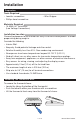
Installation Preparation Tools Required-----------------------------------------------------• Jeweller screwdriver • Wire Stripper • Phillips head screwdriver Materials Required-------------------------------------------------• 18 AWG LVT Solid Wire (Low Voltage Connections) Installation Location------------------------------------------------Choose the placement of the thermostats early in the construction process to enable proper wiring during rough-in. Consider the following: • Interior Wall.
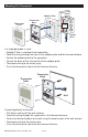
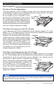
Mounting The Thermostat Adapter Plate Thermostat Front Thermostat Base Stud 3 1/4" (83 mm) Gang Box If a single gang box is used: • Adapter Plate is required (sold separately). • Feed the wiring through the hole in the adaptor plate and the thermostat base. • Fasten the adaptor plate to the gang box. • Fasten the base of the thermostat to the adaptor plate. • Terminate wiring to the wiring strip. • Push the thermostat front onto the thermostat base.
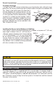
Floor Sensor 079 Installation New Installations---------------------------------------------------Thin-Set or Thin-Pour Applications If the floor covering is to be installed over either a thin-set or thin-pour material of sufficient depth, the floor sensor can be placed directly into either the thin-set material or the thin-pour material and covered over. Tiles Ensure that the sensor is located in such a Thin-set position that the attached wire is able to reach Electric to a suitable junction location.
Retrofit Installations------------------------------------------------Tile Floor Coverings If a Floor Sensor 079 is to be installed into an existing tile floor with sufficiently large grout lines, the sensor and wire can be installed in one of the grout lines between the tiles. Select a low traffic area of the floor that is Tiles mid way between the heating elements for the Thin-set sensor location.
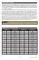
Floor Sensor 079 Testing A good quality test meter capable of measuring up to 5,000 kΩ (1 kΩ = 1000Ω) is required to measure the sensor resistance. In addition to this, the actual temperature must be measured with either a good quality digital thermometer, or if a thermometer is not available, a second sensor can be placed alongside the one to be tested and the readings compared. First measure the floor temperature using the thermometer. Disconnect the S1 and Com wires from the thermostat.
Temperature vs.
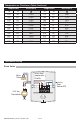
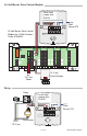
24-Volt Master Zone Control Module---------------------------------Install field jumper wire R to Rh Floor Sensor 079 No Power 519 518 C R Rh W1 S1 Com 24-Volt Master Zone Control Module for 14 Volt Actuators Order: 81006626 1 2 1 2 4 A B 1 24V 0 2 3 1 2 4 A B 1 4 1 2 4 A B 1 2 2 1 2 4 A B 1 2 5 6 1 2 4 A B 1 1 2 4 A B 1 2 2 24 V (ac) Valve Actuator RC 24 V (ac) Power Relay--------------------------------------------------------------Relay 3 4 5 6 2 1 8 7 Install field jumper wire
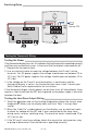
Switching Relay----------------------------------------------------- 519 518 R W Zone 1 R W Zone 2 No Power C R Rh W1 S1 Com Floor Sensor 079 R W Zone 3 24 V Com Class 2 Transformer Switching Relay X X Zone 1 H N Zone 2 H N Zone 3 H N Pump N H NL Testing the Thermostat Wiring Testing the Power--------------------------------------------------If the thermostat display turns on, this indicates that the thermostat is operating correctly and there are no electrical issues.
User Interface Home Screen Symbols Description Heat On Heat is turned on. MIN The floor is at or below the floor minimum temperature. MODE OFF The heating system is off. Warning Symbol Indicates an error is present. 11 of 16 Max The floor has reached the floor maximum temperature.
Sequence of Operation Heating Operation To change the heat temperature setting, push the or button to select a preferred temperature setting. The Heat On symbol is shown on the display when the thermostat is heating. The heat can cycle on and off within +/- 1.5°F (1°C) of the temperature setting. The floor and air heating can be shut off by holding the button until Set Room is Off.
Programmable Settings Setting User settings. Press the and advance to the next setting. Display buttons together for 3 seconds to enter and MODE Select heat or off. Range: HEAT, OFF Default: HEAT UNITS Select the temperature units. Range: °F or °C Default: °F LIGHT Select when the display back light should operate. Auto operates the backlight for 30 seconds after a keystroke. Range: OFF, AUTO, ON Default: AUTO SET FLOOR Set the floor minimum temperature.
Troubleshooting Error Messages Error Message Description Setup menu Save Error The thermostat failed to read the Programmable Settings from memory and has reloaded the factory default settings. The thermostat stops normal operation until all Programmable Settings are checked except to provide freeze protection. Room Room Room Sensor open circuit error The built-in air temperature sensor has an open circuit fault. Do not confuse this error with the auxiliary room sensor short circuit error.
Frequently Asked Questions Symptom Look for... Corrective Action Display powering on and off. Measure voltage at wiring terminals R and C. The power supply transformer may have limited VA capacity. A transformer with a larger VA rating is recommended. Thermostat does not heat. Mode Off Thermostat must be in Mode Heat in order to provide heating.
Hydronic System Electronic Controls and Thermostats Limited Warranty Watts Radiant (the Company) warrants its hydronic system electronic controls and thermostats (the Product) to be free from defects in materials and workmanship under normal usage for a period of one year from the documented date of installation of the Product. In the event of defects within the warranty period, the Company will replace the Product without charge. This remedy is the sole and exclusive remedy for breach of warranty.