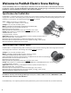
® Electric Snow Melting Mats and Cables Installation Manual Model Series SM and SC Please note that local codes may require this product and/or the control to be installed or connected by an electrician
Welcome to ProMelt Electric Snow Melting SunTouch ProMelt products are a simple way to eliminate snow and ice from surfaces. This instruction manual is provided as a guide to installing ProMelt Mat and ProMelt Cable, including design considerations, mat and cable installation, control installation, precautions, and surfacing guidelines.
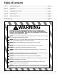
Table of Contents Phase 1 Designing the System------------------------------------------------------------------------------------- page 04 Phase 2 Preparations------------------------------------------------------------------------------------------------- page 10 Phase 3 Installing the Mat or Cable------------------------------------------------------------------------------- page 12 Phase 4 Finish Surfaces---------------------------------------------------------------------------------------------
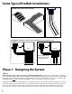
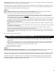
Some Typical ProMelt Installations Garage ProMelt works well for stairs and ramps. ProMelt Mats and Cables can be used in combination to fit a variety of areas. Entry Entry Garage Garage Driveway with full coverage near garage and "tire track" coverage down driveway. Phase 1: Designing the System STEP 1.
ProMelt Mat/Cable may be used to heat an outdoor area, such as a patio. This application requires special installation considerations and controls. Please see Step 1.6 for details. Heating performance is never guaranteed. The amount of heat added to the area is dependent on many factors such as air and ground temperature, wind speed, solar heat, moisture, etc. If you have any questions regarding expected performance in your application, please contact the factory. STEP 1.
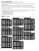
STEP 1.4 (ProMelt Mat Only) Select the ProMelt Mat(s) you need. (for ProMelt Cable sizes see next page) WATTAGE: Decide what heat output is required. Your design must consider weather conditions and how critical it is to clear the heated area. Mat with 50 watts per square foot heat output are sufficient to clear most moderate and heavy snowfall rates. Mat with 38 watts per square foot heat output are sufficient to clear most light to moderate snowfall rates.
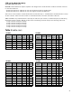
STEP 1.4 (ProMelt Cable Only) Select the cables you need. WATTAGE: Decide what heat output is required. Your design must consider weather conditions and how critical it is to clear the heated area. 50 watts per square foot: sufficient to clear most moderate and heavy snowfall rates 38 watts per square foot: sufficient to clear most light to moderate snowfall rates SIZE: Select a cable in Table 2 to fit the Heated Area measured in Step 1.2. ProMelt Cable is manufactured in a variety of sizes as shown.
STEP 1.5 (ProMelt Cable only) If the cable is to be laid on top of an existing slab, select enough Cable Strap to secure the cable to the surface. One box contains 25 ft. of strap, enough to secure about 50 sq. ft. of cable at 4-ft parallel spacing. Cable strap is usually spaced no more than 3 to 4 feet apart. STEP 1.6 Select the controls and sensors for your ProMelt Mats/Cables. Various types of controls may be used.
Outdoor Heating Application: If the ProMelt is intended to add heat to the space or objects in the area, special consideration must be given to the controls and sensing since the goal is different from snow melting. If the ProMelt is to be used for both automatic snow melting and heating, first follow the guidelines above for selecting the snow sensing and control solution. Select the desired heating control: •• A 24VAC "slab sensing" thermostat control may be used.
Phase 2: Preparations Before installing ProMelt, make sure to fully check out the products, and carefully plan your site. The following steps may not necessarily occur in the order shown, depending on contractor and electrician scheduling and variations in site preparation requirements. A good discussion with all parties involved will help eliminate costly errors and damages. INSPECT MAT/CABLE, CONTROL, and SENSOR STEP 2.1 Remove the ProMelt Mat/Cable, control, and sensor from their packages.
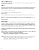
Table 3 - Mat/Cable Resistance Log Mat/Cable 1 Mat/Cable 2 Mat/Cable 3 Mat/Cable serial number Mat/Cable model number Mat/Cable voltage Mat/Cable resistance range OUT OF THE BOX BEFORE INSTALLATION Mat/Cable white 1 to white 2 Mat/Cable white 1 to ground Mat/Cable white 2 to ground AFTER MAT/CABLE IS SECURED IN PLACE Mat/Cable white 1 to white 2 Mat/Cable white 1 to ground Mat/Cable white 2 to ground AFTER COVERINGS ARE APPLIED Mat/Cable white 1 to white 2 Mat/Cable white 1 to ground Mat/Cable white 2
STEP 2.9 Paver or Stone Applications Follow guidelines recommended by the paver manufacturer. If a coarse of sand is to be applied over the gravel base, the mat/cable must first be secured in place and then covered with a minimum 1-1/2 inch layer of sand to completely embed the mat. STEP 2.10 Ceramic or Stone Tile Applications ProMelt mats or cables can be installed in the structural slab or in a thick mortar bed above a structural slab.
time between stages, as the slab should not be allowed to fully cure or the asphalt to completely cool. Therefore, if using ProMelt Cable, you may want to lay it out and tie it to rewire that can be quickly lifted into place after the first stage is laid. This might also be preferable for a mat installation, although if mats are precut and shaped to the area, they generally can be rolled into place fairly quickly.
STEP 3.6 Stone or Paver Application ProMelt Mat: Begin laying out the mat and secure it onto the base with landscape fabric stakes or similar over the mat tape every 2 feet or so. Make sure it is laid flat. Do not use metallic stakes or staples directly over the heating cable. Be careful not to damage the heating cable. ProMelt Cable: Secure plastic mounting cable ties to the gravel base, driving long nails or similar through the head of the cable tie.
STEP 3.9 Use a digital multi-meter to measure the resistance between the conductors and ground wire of the mat/cable power leads again. Record these resistances in Table 3 under “After mat/cable is secured in place”. STEP 3.10 Feed the power leads through the conduit into the junction box, leaving at least 6 inches of free lead length. Secure the heating cable and splice so that they will not be pulled into the conduit.
STEP 3.14 Expansion Joints: ProMelt heating cable must never be run through an expansion joint. Doing so may cause damage to the cable with slab movement. It is recommended to lay the mat so these joints are avoided. However, if it is necessary, a portion of the heating cable may be dropped into the grade below the expansion joint as shown. Fill around the cable with at least 1 inch thick sand.
STEP 4.2 1-1/2" to 3" of concrete above ProMelt. Concrete Application Pour concrete over the base and ProMelt Mat/Cable so that no less than 1-1/2 inches and no more than 3 inches covers the top of the heating cables. The slab should be a minimum of 4 inches thick total. Driveways normally require thicker. Follow building code requirements for required thicknesses. CAUTION: Do not use sharp tools which could damage the ProMelt.
Step 4.5 Ceramic or Stone Tile Applications For either application below, exterior-grade materials should be selected and installed per manufacturer’s recommendations. Only vitreous (non-porous) tile should be used as other tile will absorb moisture which will lead to failure. The maximum thickness above the cable should be no less than 1.5 and no more than 2.5”. A movement joint should be installed between any heated and non-heated area. 1-1/2" to 2.
Troubleshooting If not qualified to perform electrical installations, it is strongly recommended that a qualified, licensed electrician be hired to install the heating cables and related electrical components. If problems with the system arise, please consult the troubleshooting guide below. Any troubleshooting work should be done with the power removed from the circuit, unless otherwise indicated. Call the factory for further assistance (see contact information on back cover).
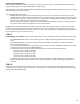
Appendix: Typical Wiring Diagrams Following are examples of typical wiring connections for the ProMelt systems. Carefully read and follow the instructions given with each control for complete information. All electrical work must be performed by a qualified personnel, in accordance with local codes, ANSI/NFPA 70(NEC Article 426) and section 62 of the CEC part 1.
Wiring for optional Outdoor Heating Thermostat.
4500 E. Progress Place Springfield, MO 65803 Phone: (417) 522-6128 Toll Free USA, Canada: (888) 432-8932 On the Web: www.suntouch.com ©2009-2011 Watts Radiant Inc.