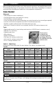
SlabHeat™ Installation Manual Series SH Assembled in the USA Please be aware local codes may require this product and/or the thermostatic control to be installed or connected by an electrician. Please leave this manual with the end user.
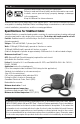
Read this Manual BEFORE using this equipment. Failure to read and follow all safety and use information can result in death, serious personal injury, property damage, or damage to the equipment. Keep this Manual for future reference. SlabHeat products are a simple way to heat a given space. This instruction manual is provided as a guide to installing SlabHeat Cable, including design considerations, cable installation, control installation, precautions, and floor covering guidelines.
Table of Contents Important Safety Information.....................3 Phase 1 - Preparations ..............................5 Phase 2 - Electrical Rough-in ..................10 Phase 3 - Cable Installation .....................12 Phase 4 - Finish Coverings ......................14 Phase 5 - Control Installation ..................16 Appendices ..............................................17 Troubleshooting .......................................24 Warranty ...................................................
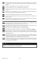
NEVER install the heating cable under cabinets or other built-ins having no floor clearance, or in small closets. Excessive heat will build up in these confined spaces and cause damage. NEVER pull any of the heating cable or factory splices into any conduit. NEVER forget to install the floor sensor included with the thermostat. NEVER install the heating cable in walls, over walls or partitions that extend to the ceiling, or in closets.
Phase 1 - Preparations Before installing SlabHeat, make sure to fully inspect the products, and carefully plan your site. The following steps may not necessarily occur in the order shown, depending on contractor and electrician scheduling and variations in site preparation requirements.
Inspect cable, control, and sensor To prevent the risk of personal injury and/or death, make sure power is not applied to the product until it is fully installed and ready for final testing. All work must be done with power turned off to the circuit being worked on. STEP 1.1 Remove the SlabHeat Cable, SunStat control, and SunStat sensor from their packages. Inspect them for any visible damage and verify everything is the correct size and type according to the plan and order.
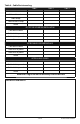
Table 4 - Cable Resistance Log Cable 1 Cable 2 Cable 3 Cable serial number Cable model number Cable voltage Cable resistance range Sensor OUT OF THE BOX BEFORE INSTALLATION Cable white to white Cable white to ground Cable white to ground Sensor AFTER CABLE IS SECURED IN PLACE Cable white to white Cable white to ground Cable white to ground Sensor AFTER SLAB IS POURED Cable white to white Cable white to ground Cable white to ground Sensor Retain this log to retain the warranty! Do not discard! INSTALLATI
BASE MATERIAL STEP 1.5 Prepare the site that you want to heat with SlabHeat Cable. This includes making sure all utilities and obstructions are accounted for. STEP 1.6 New concrete slab: Lay a smooth, well-compacted gravel base. Ensure proper slope and drainage as required by local building codes to avoid water buildup in any heated or surrounding areas. Follow local building code and construction guidelines for grade thickness and type.
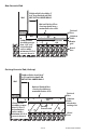
New Concrete Slab Wall SlabHeat Cable should be 4" to 6" from finished wall. DO NOT INSTALL UNDER WALLS. Optional finished floor covering should have a maximum R value of R3. Finished floor SlabHeat Cable SlabHeat Cable should be no more than 1-1/2" to 2" below finished surface with a minimum of 3/4" of concrete above it. Concrete slab Rewire grid Gravel base Existing Concrete Slab (slab cap) SlabHeat Cable should be 4" to 6" from finished wall. DO NOT INSTALL UNDER WALLS.
Phase 2 - Electrical Rough-in To prevent the risk of personal injury and/or death, make sure power is not applied to the product until it is fully installed and ready for final testing. All work must be done with power turned off to the circuit being worked on. STEP 2.1 Circuit Breaker (Overcurrent Protection) SlabHeat installations must be protected against overload by a circuit breaker.
STEP 2.3 Power Lead Conduit Install a minimum of 3/4" rigid or flexible Listed conduit from the control electrical box or junction box to the slab location. Extend it 2" to 6" into the slab edge and attach a bushing to the end to prevent damaging the cable power leads. STEP 2.4 Sensor Conduit The SunStat sensor is designed to be embedded in the slab. However, it is recommended that the sensor be installed in a minimum of 1/2" rigid or flexible Listed conduit for added protection.
Phase 3 - Cable Installation The following Steps 3.1 through 3.8 cover installation basics. Step 3.9 covers some specific applications and their special requirements. BASIC INSTALLATION STEP 3.1 Determine a time to install the cable when equipment, heavy tools, and site traffic will be minimal to keep from possibly damaging the product. Be prepared to apply the surfacing courses over the cable the same day so it will be protected from damage.
If installing on top of existing slab, secure CableStrap to the surface. Use nails or similar, every 6 to 10 inches. CableStrap should be placed at either end of the heated area, and additional straps should be applied every 3 to 4 feet in between to hold the cable in place during surfacing. STEP 3.5 Use a digital multi-meter to measure the resistance between the conductors of the cable power leads again. Record these resistances in Table 4 under “After cable is secured in place". STEP 3.
SPECIAL APPLICATIONS STEP 3.9 Expansion Joints: Heating cable must never be run through an expansion joint. Doing so may cause damage to the cable with slab movement. It is recommended to lay the cable so these joints are avoided. However, if it is necessary, a portion of the heating cable may be dropped into the grade below the expansion joint as shown. Fill around the cable with at least 1 inch thick sand.
STEP 4.2 Pour concrete over the base and SlabHeat Cable so that there is a minimum of 3/4" of material above the heating cable. The SlabHeat Cable should be no more than 1-1/2" to 2" below the top finished surface of the floor. Do not use sharp tools which could damage the SlabHeat cable. Blunted shovels should allow you to work the concrete carefully into all areas. Make sure the heating cable is fully embedded, as well as 2 to 6 inches of the conduit(s) enclosing the power lead and slab sensor wiring.
Phase 5: Control Installation STEP 5.1 Install the Controls If it has not already been done, install an electrical box for the SunStat thermostat and SunStat Relay. See Step 2.2 for details. STEP 5.2 Read and follow the instructions included with the SunStat thermostat and SunStat Relay for complete connection instructions, requirements, and mounting. The ground wire supplied with the cable must be connected to a suitable grounding/earthing terminal. STEP 5.
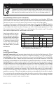
Appendix - Typical SlabHeat Installations These illustrations show some of the typical installation locations of SlabHeat. In addition to these, SlabHeat is also well suited for any kind of home addition with concrete slab. It's perfect for a bedroom addition, a sun room, a detached garage, or an extended living area. SlabHeat also works well for use in commercial areas.
Garage Storage IOM-WR-SH 1528 18 of 24
Finished Basement Unfinished Mechanical Area 19 of 24 © 2015 Watts Radiant
Connecting Multiple Cables To prevent the risk of personal injury and/or death, do not perform any electrical work unless qualified to do so. Work should be done with great care and with power turned off to the circuit being worked on. Follow all local building and electrical codes.
Troubleshooting Guide If problems arise with the system or its related electrical components, please consult this troubleshooting guide. If not qualified to perform electrical work, it is highly recommended a qualified, licensed electrician be hired. Any electrical troubleshooting work should be performed with the power removed from the circuit, unless otherwise noted. Although this troubleshooting guide is provided to assist with problems experienced with a system, results are never guaranteed.
Problem Possible Cause Floor heats continuously. Incorrect wiring. The control was “bypassed” when it was wired to the power supply. Defective control. Floor temperature shows much higher than what the floor feels like. Floor sensor is not wired properly, or is located incorrectly. Solution Make sure wiring connections are correct. Consult the wiring diagram on the back of the control, the instructions that came with the control, or the wiring diagrams in Appendix 2.
Electric Floor-warming Products 25-year Limited Warranty SunTouch and Watts Radiant (the Companies) warrant their respective electric floor heating mats and cables (the Products) to be free from defects in materials and workmanship for twenty-five (25) years from the date of manufacture. Thermostats and controls sold by the Companies are warranted, parts and materials, for two (2) years from the date of purchase. The sole remedy for controls is product replacement.
Affiliations: SunTouch Customer Support USA Toll-free: (888) 432-8932 USA Fax: (417) 831-4067 Canada Toll-free: (888) 208-8927 Canada Fax: (905) 332-7068 Latin America Tel: (52) 81-1001-8600 Latin America Fax: (52) 81-8000-7091 SunTouch.com The SunTouch and Watts Radiant manufacturing facility’s Quality System is an ISO 9001:2008 registered facility through LRQA. 8 40213 20753 IOM-WR-SH 1528 Watts Radiant Customer Support USA Toll-free: (800) 276-2419 USA Fax: (417) 864-8161 WattsRadiant.