
Install Instructions

IOM-WR-SH 1528 6 of 24
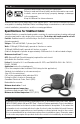
Inspect cable, control, and sensor
To prevent the risk of personal injury and/or death, make sure power is not
applied to the product until it is fully installed and ready for final testing. All
work must be done with power turned off to the circuit being worked on.
Megohmeters apply high voltage and could shock or cause serious injury if improperly
used. Follow megohmeter instructions for safe and proper use.
Temperature Typical Values
55°F (13°C) 17,000 ohms
65°F (18°C) 13,000 ohms
75°F (24°C) 10,000 ohms
85°F (29°C) 8,000 ohms
Table 3 - Floor Sensor Resistance Values
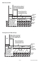
STEP 1.1
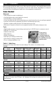
Remove the SlabHeat Cable, SunStat control, and SunStat sensor from their packages. Inspect
them for any visible damage and verify everything is the correct size and type according to
the plan and order. Do not attempt to install a damaged product.
STEP 1.2
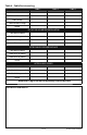
Record the cable information in Table 4. Give this information to the homeowner to keep in
a safe place.
The cable model number, serial number, voltage, and resistance range are shown on a
nameplate label attached to the power leads. Do not remove this nameplate label. The
electrical inspector will need to see this.
STEP 1.3
Use a digital multi-meter set to the 200Ω or 2000Ω (2kΩ) range to measure the resistance
between the conductors of the cable power leads. Record these resistances in Table 4 under
“Out of the box before installation”.
The resistance between the white lead wires should be within the resistance range on the
nameplate label. If it is a little low, it may be due to low air temperatures or meter calibration.
Consult the factory if in doubt.
The resistance between either of the white leads and ground lead should be “open”, usually
indicated by an “OL” or a “I”. This is the same as displayed when the test leads are not touching
anything. If there is any change in the reading, record this information and contact the factory
before installing. This could indicate damage, test lead problems, or a number of other issues.
Try “pinning” the test leads to the cable lead wires against a hard non-metal surface if your
readings fluctuate.
Change the meter to the 20,000 ohms (20
kΩ) range. Measure between the lead wires
of the floor sensor. This resistance varies
according to the temperature sensed at the
tip. Table 3 provides approximate values for
comparison.
STEP 1.4
Qualified Electrician Only: It is highly recommended that your electrician perform an insulation
resistance test on the cable. A megohmeter (e.g. Megger
®
) adjusted to a minimum 1000 VDC
should give a measured value at least 20 megohm (MΩ). This test will expose any minor damage
to the cable that is undetectable by a standard multi-meter.